Numerical-control forming mold
A technology for forming molds and controllers, applied in the directions of forming tools, manufacturing tools, cleaning methods and utensils, etc., can solve problems such as precision errors and parts cannot be rotated, and achieve the effect of improving forming quality and forming accuracy.
- Summary
- Abstract
- Description
- Claims
- Application Information
AI Technical Summary
Problems solved by technology
Method used
Image
Examples
Embodiment 1
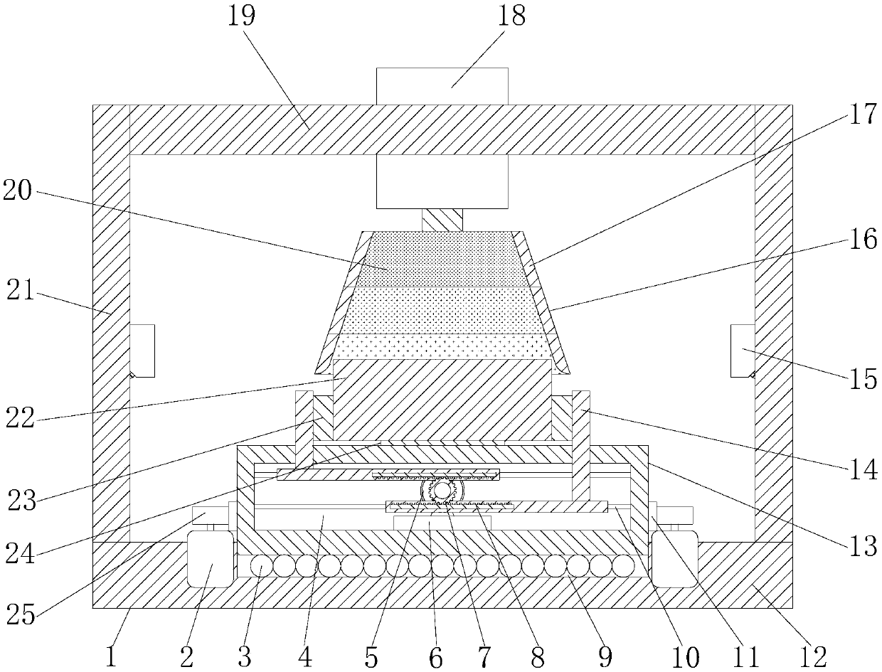
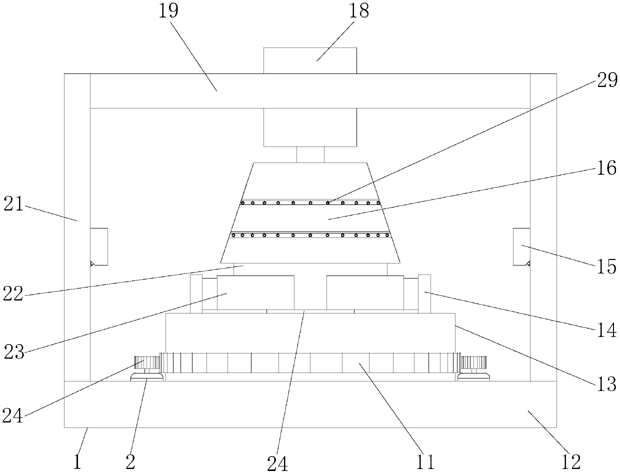
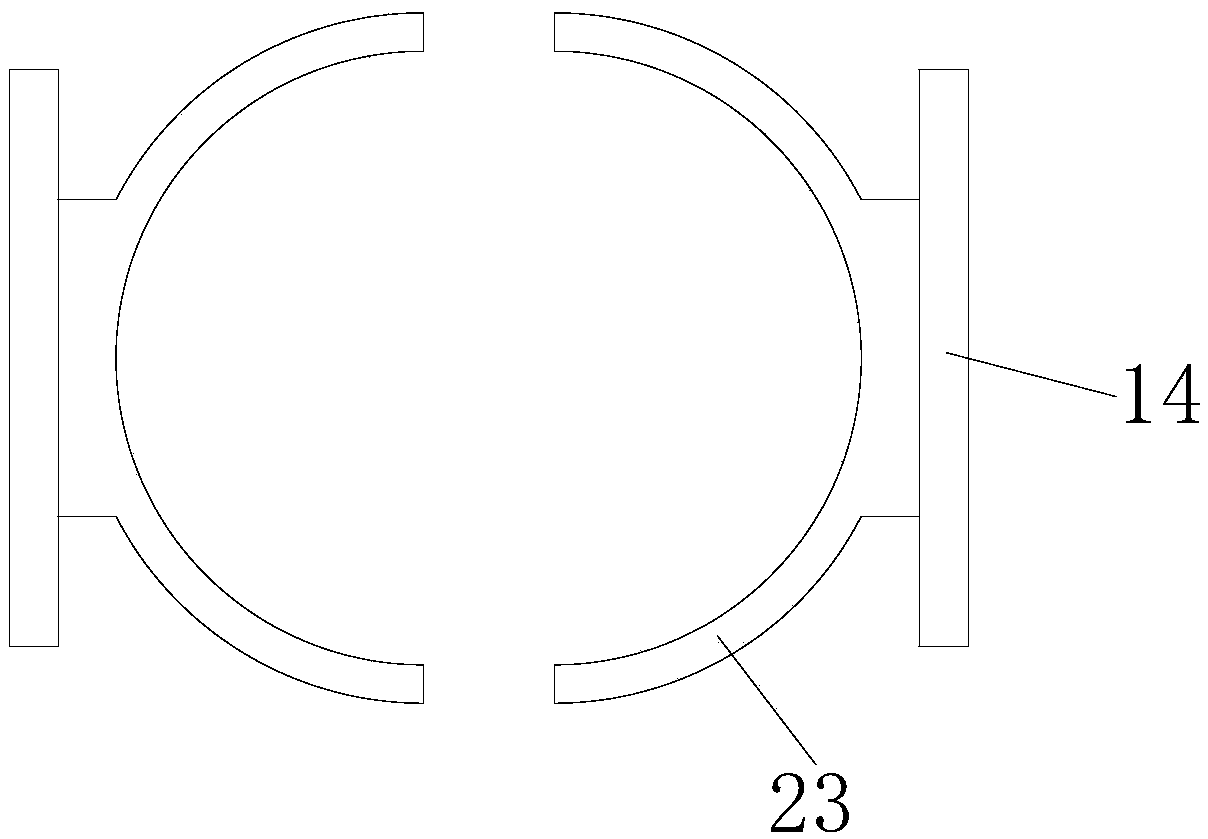
[0057] see figure 1 , figure 2 as well as image 3 , the present embodiment provides a numerical control forming mold, which includes a frame 1, an upper mold 16, a lower mold 24, a rotating platform 13, a driving mechanism, a clamping mechanism, a photoelectric sensor 15 and a main controller.
[0058] In this embodiment, the outer profile of the frame 1 is a cuboid, and the frame 1 includes a bottom plate 12 , a support column 21 and a top plate 19 . The base plate 12 is provided with a cylindrical groove 9, and the base plate 12 can be placed on the ground or other equipment. The support column 21 is installed on the base plate 12, and the top plate 19 is connected with the base plate 12 through the support column 21, thereby forming a stable whole. Positioning blocks are provided in the middle of the two opposite support columns 21 , and when the parts 22 are placed on the frame 1 , the parts 22 can be positioned by the positioning blocks. The size of the frame 1 can ...
Embodiment 2
[0070] see Figure 4, this embodiment provides a digital forming die, which is similar to the numerical control forming die in Embodiment 1, the difference is that the mechanism of the driving mechanism is different. In this embodiment, the driving mechanism includes a third motor 26, a third gear 27, an inner ring gear 28 and a rolling assembly. The third motor 26 is installed on the base plate 12 and coaxially arranged with the cylindrical groove 9 , and the third gear 27 is sleeved on the output shaft of the third motor 26 . The inner ring gear 28 is installed in the blind hole provided at the bottom of the rotating platform 13 and meshes with the third gear 27 . The rolling assembly includes an annular sleeve 37 and a plurality of rolling balls 3 arranged in the annular sleeve 37 . The annular sleeve 37 is arranged coaxially with the cylindrical groove 9 and is located in the cylindrical groove 9 ; the rolling ball 3 is located on the bottom wall of the cylindrical groov...
Embodiment 3
[0073] see Figure 5 as well as Figure 6 , This embodiment provides a digital molding die, which adds an alarm device 1 on the basis of Embodiment 1. The alarm device one includes a trigger switch 30, an alarm one and a buffer. The trigger switch 30 is installed on the rotary platform 13 and is located on the path of the upper mold 16 lifting. The alarm one is set on the frame 1 and is electrically connected to the trigger switch 30 . The alarm one is connected to a power supply through the trigger switch 30; the trigger switch 30 is triggered when the bottom of the upper mold 16 descends to the rotary platform 13, so that the alarm one receives the power supply to send corresponding alarm information. When patrix 16 descends excessively, patrix 16 descends and can bump trigger switch 30, and trigger switch 30 can open alarm one, thereby reminds operator to stop the descending of patrix 16, protects numerical control forming mould.
[0074] The buffer includes a positioni...
PUM
 Abstract
Description
Claims
Application Information
 - R&D
- Intellectual Property
- Life Sciences
- Materials
- Tech Scout
- Unparalleled Data Quality
- Higher Quality Content
- 60% Fewer Hallucinations
Browse by: Latest US Patents, China's latest patents, Technical Efficacy Thesaurus, Application Domain, Technology Topic, Popular Technical Reports.
© 2025 PatSnap. All rights reserved.Legal|Privacy policy|Modern Slavery Act Transparency Statement|Sitemap|About US| Contact US: help@patsnap.com


