
Liquefied foundation treatment method based on building garbage

A technology of construction waste and liquefied foundation, which is applied in the direction of construction, foundation structure test, soil protection, etc. It can solve the problems of insignificant soil squeezing effect and easy collapse of pile holes, achieve obvious reinforcement effect, reduce mud discharge, avoid The effect of complex construction procedures

Inactive Publication Date: 2019-04-26
HAINAN UNIVERSITY
View PDF7 Cites 4 Cited by
  • Summary
  • Abstract
  • Description
  • Claims
  • Application Information

AI Technical Summary

Problems solved by technology

[0004] The purpose of the present invention is to address the above-mentioned deficiencies in the prior art, to provide a liquefied foundation treatment method based on construction waste, to provide a new construction waste treatment method, and to solve the construction problems caused by the traditional compacted sand and gravel pile method. The effect of compacting soil is not obvious when the diameter is small, avoiding the defects of mud generated in the construction process of traditional vibrating method, and the formed pile holes are easy to collapse without support, etc.

Method used


Image

  • Liquefied foundation treatment method based on building garbage
  • Liquefied foundation treatment method based on building garbage
  • Liquefied foundation treatment method based on building garbage

Examples


Embodiment Construction

[0033] The specific embodiments of the present invention are described below to facilitate those skilled in the art to understand the present invention, but it should be clear that the present invention is not limited to the scope of the specific embodiments. For those of ordinary skill in the art, as long as various changes Such changes are obvious within the spirit and scope of the present invention as defined and determined by the appended claims, and all inventions and creations utilizing the inventive concept are within the scope of protection.

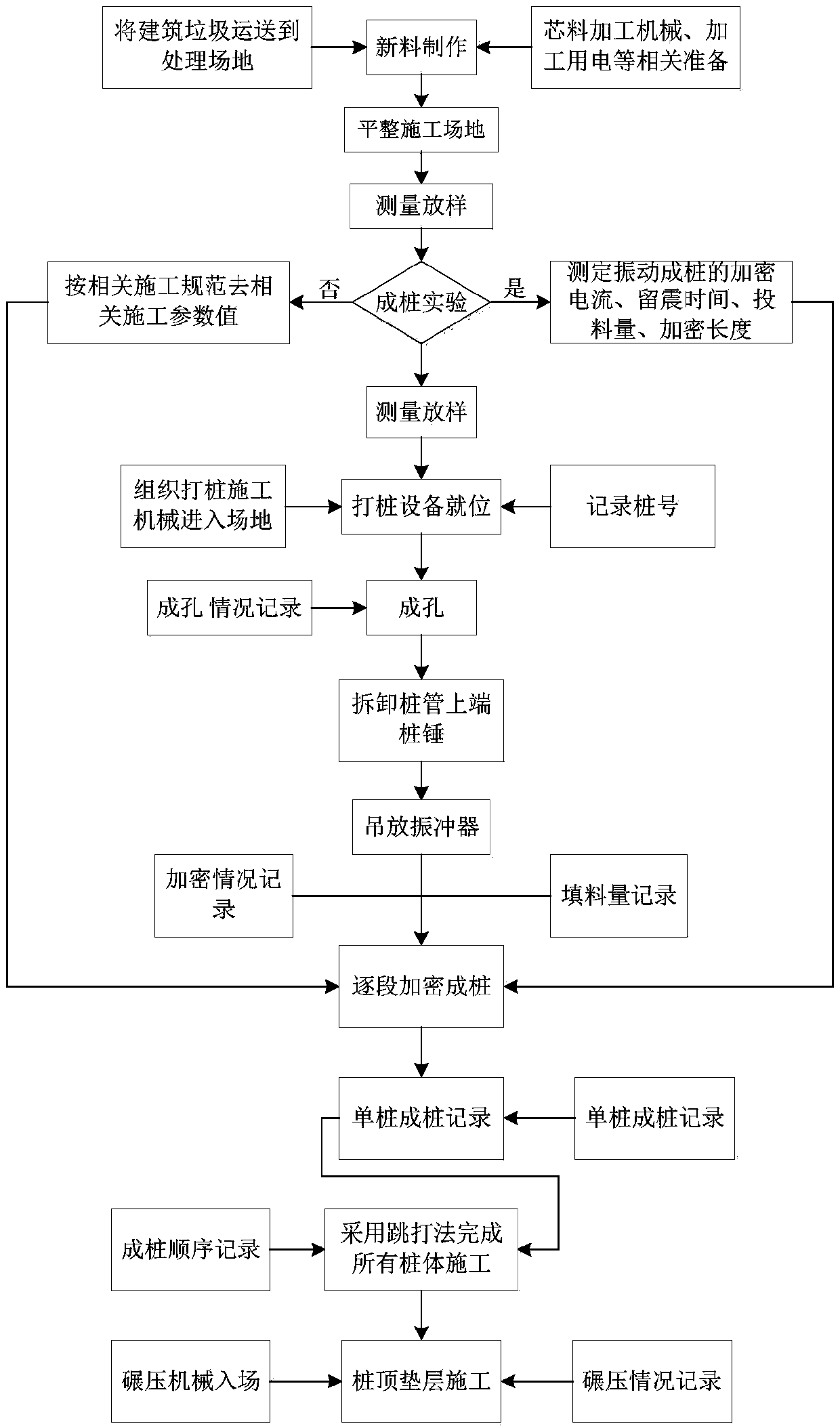
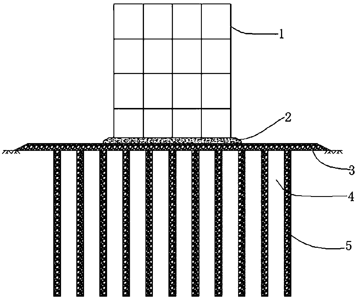
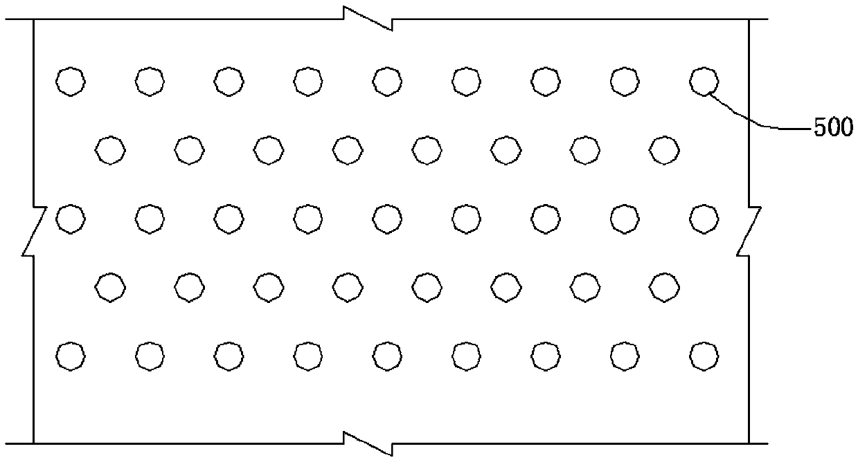
[0034] According to one embodiment of the present application, reference is made to Figure 1-Figure 7 , the construction waste-based liquefaction foundation treatment method of this scheme includes:

[0035] S1. Remove the white garbage in the construction waste, crush the construction waste and transport it to the construction site;

[0036]The specific methods include: transporting construction waste generated from demolition...


PUM


Abstract

The invention discloses a liquefied foundation treatment method based on building garbage. The liquefied foundation treatment method comprises the following steps of crushing the building garbage, andtransporting to a construction site; performing pile-forming test around a construction consolidated foundation site; measuring and lofting according to a pile diagram of building garbage piles; drilling pile driving holes by a steam pile driver and a guide pile driver; driving pile pipes to the preset depth of the treated foundation; feeding a core material with thickness of 80 to 100 cm into each pile hole, lifting each pile pipe until a contact coverage height of 20 cm is formed between the bottom of the pile pipe and the particle material, and placing a vibroflotation device to the bottompart of each pile hole via a sinking pipe; starting the vibroflotation device to maintain vibroflotation for 10 to 20 s, continuously feeding the material, and lifting the vibroflotation device and each pipe pile in a synchronous staged lifting way in the construction process of the pile body, wherein the lifting height is 30 cm in each stage, and the vibroflotation maintaining time of the vibroflotation device is 10 to 20 s until the construction of the pile body is completed; repeating the step S7, constructing by sections from bottom to top until the hole is reached, and recording the feeding quantity and vibroflotation maintaining time at the corresponding depth of each section; completing the construction of all pile bodies by a jump driving method; constructing a bedding layer of the pile top by a flat rolling method.

Description

technical field [0001] The invention belongs to the technical field of construction waste treatment, and in particular relates to a construction waste-based liquefaction foundation treatment method. Background technique [0002] Hainan Province is surrounded by the sea on all sides, and its large-scale building foundations are composed of sandy soil. Under the action of earthquake load, the sandy soil foundation is very easy to liquefy, the foundation is greatly deformed, and the superstructure is easily damaged. Under the action of some dynamic loads, the built buildings will not be damaged due to the liquefaction of the foundation. In the project, most of the construction wastes generated in the process of building reconstruction, demolition and new construction are piled up, landfilled and processed into recycled aggregates. At present, there is no reasonable disposal method. , The construction waste generated by the demolition will be more and more, and the problem of ...

Claims


Application Information

Patent Timeline
Patent Type & Authority Applications(China)
IPC IPC(8): E02D3/00E02D33/00E02D7/26E02D5/72
CPCE02D3/00E02D5/72E02D7/26E02D33/00
Inventor 何旭王志佳施杰谢森林酒文静
Owner HAINAN UNIVERSITY
Learn More