Installation structure and building method of cantilever scaffold bottom platform

A technology of cantilevered scaffolding and bottom platform, which is applied to the attachment of scaffolding, housing structure support, housing structure support, etc., can solve the problem of unsuitable traction force, and achieve the effect of low welding difficulty, easy installation, and uniform stress dispersion.

Active Publication Date: 2019-04-26
江苏精享裕建工有限公司
View PDF8 Cites 1 Cited by
  • Summary
  • Abstract
  • Description
  • Claims
  • Application Information

AI Technical Summary

Problems solved by technology

[0003] Although this construction method can provide a cantilevered formwork platform installation structure and its construction method with clear force transmission system, good structural integrity, uniform force, high connection strength, and convenient construction, the patent uses anchor steel plates or The counterweight pulls multiple sets of stay cables, all of which pass through the same reserved hole and are connected to the cantilevered steel, which can easily lead to the incompatibility between the traction force of the stay cables on the cantilevered

Method used


Image

  • Installation structure and building method of cantilever scaffold bottom platform
  • Installation structure and building method of cantilever scaffold bottom platform
  • Installation structure and building method of cantilever scaffold bottom platform

Examples


Embodiment 1

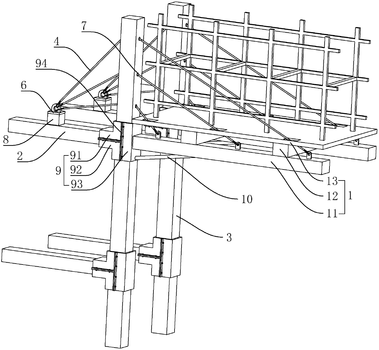
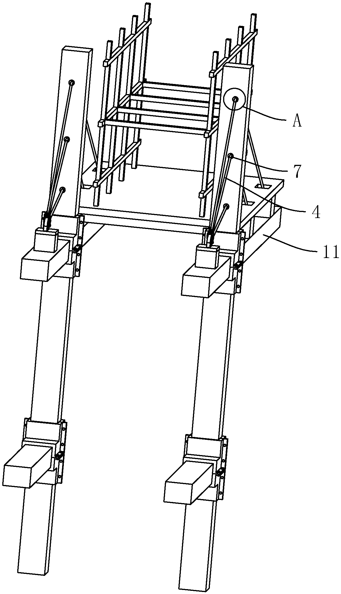
[0045] Embodiment 1: An installation structure and construction method of a platform at the bottom of a cantilevered scaffold, such as figure 1 As shown, it includes cantilevered steel 11 , horizontal support frame 12 , platform plate 13 , stay cables 4 , reserved holes 7 , supporting steel casing 9 and anchor steel plate 6 . Wherein, the stay cable 4 is related to the connection position of the cantilever shaped steel 11 and the set position of the reserved hole 7, so that the stay cable 4 can reasonably distribute the traction force to the cantilever shaped steel 11.

[0046] The horizontal support frame 12 is arranged on the top of the cantilevered steel 11, and the platform plate 13 is arranged on the horizontal support frame 12, and the platform plate 13, the horizontal support frame 12 and the cantilevered steel 11 together form the platform 1 at the bottom of the cantilevered scaffold.

[0047]The anchoring steel plate 6 is fixedly arranged on the frame beam 2 , and the...

Embodiment 2

[0054] Embodiment 2: A method for building a platform at the bottom of a cantilevered scaffold, comprising the following steps:

[0055] Step 1: making embedded parts, respectively making the first part 91, the second part 92 and the third part 93 of the supporting steel casing 9 according to the design requirements;

[0056] Step 2: Connect the embedded parts with the frame structure, install the first part 91, the second part 92 and the third part 93 of the supporting steel casing 9 to the nodes of the frame column 3 and the frame beam 2, and assemble them according to the design requirements;

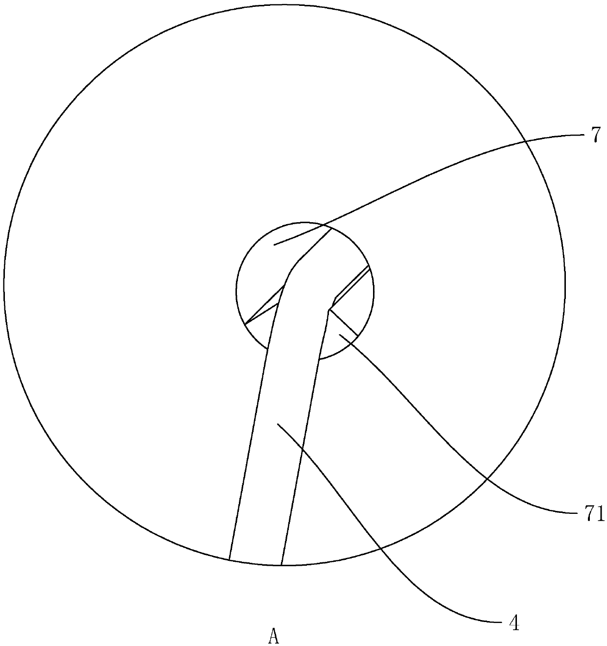
[0057] Step 3: pouring the frame structure, pouring the frame structure, and arranging the reserved holes 7 and the protection sheet 71 on the frame column 3 according to the design requirements;

[0058] Step 4: Make the supporting rods and the cantilevered steel 11, weld the end plates at the ends of the cantilevered steel 11 and the supporting inclined bar 10, and reserve bolt hol...


PUM

PropertyMeasurementUnit
Central angleaaaaaaaaaa

Abstract

The invention belongs to the field of structural engineering, and provides an installation structure and building method of a cantilever scaffold bottom platform. According to the technical scheme, the structure is characterized by including cantilever profile steel, horizontal supporting skeletons which are arranged above the cantilever profile steel in a parallel mode, a platform board which isarranged above the horizontal supporting skeletons, a plurality of stay cables which are arranged above the cantilever profile steel and connected with the cantilever profile steel, preserved holes capable of making the stay cables penetrate through frame columns, and anchoring steel plates which are connected with the stay cables and provide fixing for the stay cables, wherein the number of the preserved holes is great, and vertical distance between one arbitrary preserved hole and a fixing point of the end, away from the cantilever profile steel, of the corresponding stay cable satisfies theequation: 1=L*(a/A)2. The platform has the advantage that through the stay cables, traction can be distributed on the cantilever profile steel reasonably.

Description

technical field [0001] The invention relates to the field of structural engineering, in particular to an installation structure and a construction method for a bottom platform of a cantilevered scaffold. Background technique [0002] At present, the Chinese patent with the publication number CN104389419B is a cantilevered formwork platform installation structure and construction method. One end of the cantilevered steel is fixed on the supporting steel casing at the beam-column node, and a plurality of supporting diagonals are set between the bottom and the frame column. Rods; stay cables are set above the cantilevered steel, and the other end of the stay cables is connected with the anchor steel plate; beam-column support rods are set between the beams and columns; system. The cantilevered formwork platform supports and pulls together, the force transmission system is clear, and the permanent components of the building are fully utilized, which has good economic benefits. ...

Claims


Application Information

Patent Timeline
IPC IPC(8): E04G5/04E04G5/00E04G5/16
CPCE04G5/006E04G5/046E04G5/16
Inventor 钟成福周红星欧阳圣文
Owner 江苏精享裕建工有限公司
Why Eureka
Try Eureka