
Multi-heat-source phase change heat dissipating device

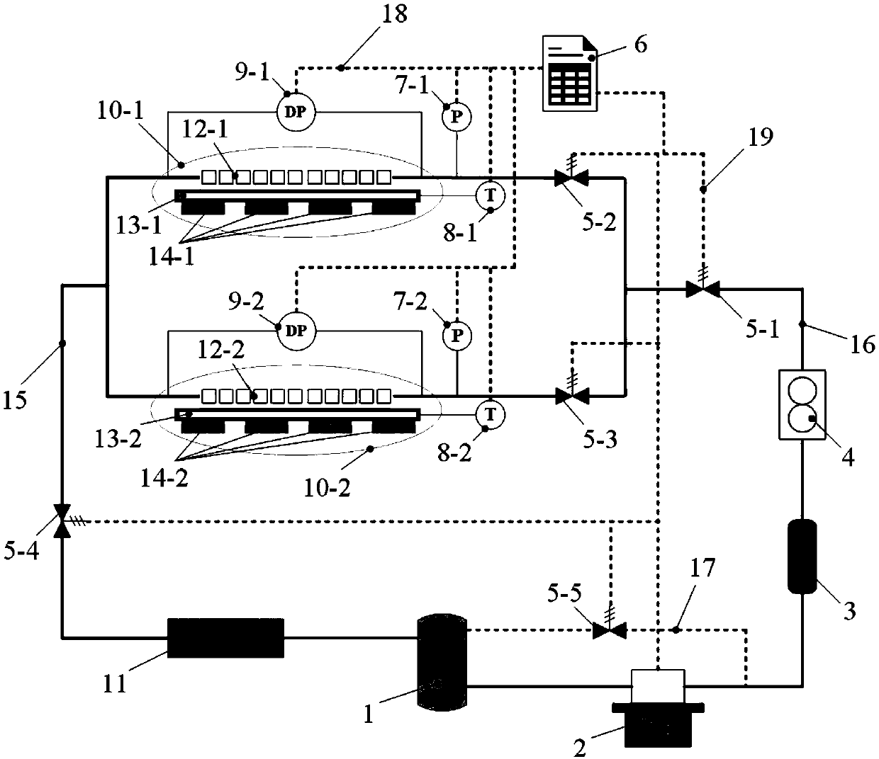
A multi-heat source, phase-change heat technology, applied in the fields of electronic cooling, high-efficiency heat exchange, and thermal engineering, can solve problems such as affecting the working performance of devices and equipment, uneven temperature distribution on the heat dissipation surface, and increasing demand for cooling fluid flow rate. , to achieve the effect of good temperature uniformity, less cooling medium demand, and low system power consumption and noise level

Inactive Publication Date: 2019-04-26
BEIJING JIAOTONG UNIV
View PDF4 Cites 2 Cited by
  • Summary
  • Abstract
  • Description
  • Claims
  • Application Information

AI Technical Summary

Problems solved by technology

Although the cooling capacity of single-phase liquid cooling technology can reach 20W / cm 2 , but for the heat dissipation requirements of higher heat flux, especially for the heat dissipation of multi-heat source and high heat flux chips in the process of networked and intelligent development of high-performance supercomputers such as cloud computing and data centers, single-phase liquid cooling technology has many problems. Large limitations, such as: the increase in the flow rate of the cooling medium increases the pump power and noise; there is a temperature rise in the single-phase flow of the cooling medium, which makes the temperature distribution of the heat dissipation surface uneven, affecting the normal operation of devices and equipment Performance, so it cannot be well adapted to the limitations of application conditions such as heat dissipation load, system power consumption, installation space, and noise level
At present, the micro-channel phase change cooling technology has great advantages in the heat dissipation of high heat flux devices and equipment, but considering the heat dissipation requirements of multiple heat sources and even at the system level, there are still heat peaks of heat sources and uneven flow distribution of heat sinks. Issues affecting and restricting heat dissipation effects such as phase flow instability

Method used


Image

  • Multi-heat-source phase change heat dissipating device

Examples


Embodiment Construction

[0020] Embodiments of the present invention are described in detail below, examples of which are shown in the drawings, wherein the same or similar reference numerals denote the same or similar elements or elements having the same or similar functions throughout. The embodiments described below by referring to the figures are exemplary only for explaining the present invention and should not be construed as limiting the present invention.

[0021] Those skilled in the art will understand that unless otherwise stated, the singular forms "a", "an", "said" and "the" used herein may also include plural forms. It should be further understood that the word "comprising" used in the description of the present invention refers to the presence of said features, integers, steps, operations, elements and / or components, but does not exclude the presence or addition of one or more other features, Integers, steps, operations, elements, components, and / or groups thereof. It will be understoo...


PUM


Abstract

The embodiment of the invention provides a multi-heat-source phase change heat dissipating device which comprises a liquid storing tank, a pump, a filter, a flow meter, a multi-heat-source phase change heat management unit for gradient composite heat exchange, a condenser, a liquid return pipeline and a liquid supply pipeline. The multi-heat-source phase change heat dissipating device is applicable to heat dissipating of multi-heat-source chips with high heat flow density, devices or equipment, according to the characteristic of multiple heating parts, based on the phase change heat managementunit for gradient composite heat exchange and other distribution application forms, corresponding group control strategies are combined, and it is ensured that the multiple heating parts are locatedwithin the reasonable temperature range.

Description

technical field [0001] The invention relates to the technical fields of electronic cooling, high-efficiency heat exchange, and thermal engineering, in particular to a multi-heat source phase-change heat dissipation device. Background technique [0002] With the advancement and development of science and technology, emerging electronic equipment and mechanical components such as high-performance supercomputers, radar and laser devices, high-speed train traction converters, and MEMS systems are gradually miniaturized. , has become a bottleneck restricting the continued development of the industry. The cooling capacity of traditional forced air cooling technology generally does not exceed 1W / cm 2 , is no longer applicable to the cooling problem of high heat flux devices and equipment. Although the cooling capacity of single-phase liquid cooling technology can reach 20W / cm 2 , but for the heat dissipation requirements of higher heat flux, especially for the heat dissipation o...

Claims


Application Information

Patent Timeline
Patent Type & Authority Applications(China)
IPC IPC(8): F28D15/04F28D15/06
Inventor 贾力党超
Owner BEIJING JIAOTONG UNIV
Learn More