
Terahertz super-resolution imaging system and method based on confocal waveguide

A super-resolution imaging and imaging system technology, applied in microscopes, optics, instruments, etc., can solve the problems of terahertz wave energy loss, difficulty in achieving super-resolution imaging, and inability to break through the diffraction limit, and achieve the effect of reducing transmission loss.

Inactive Publication Date: 2019-04-26
龚诚
View PDF0 Cites 0 Cited by
  • Summary
  • Abstract
  • Description
  • Claims
  • Application Information

AI Technical Summary

Problems solved by technology

[0003] However, although confocal technology can improve the imaging quality, it is limited by the traditional lens imaging theory. High spatial frequencies cannot be effectively transmitted and cannot break through the diffraction limit. The imaging resolution is about 1 to 4 times the wavelength, and it is difficult to achieve ultra- resolution imaging
Moreover, there is a large loss in the terahertz lens, and the water vapor in the free space will also cause absorption loss to the terahertz. Therefore, the confocal lens imaging system based on the free space will cause a large loss of terahertz wave energy.

Method used


Image

  • Terahertz super-resolution imaging system and method based on confocal waveguide
  • Terahertz super-resolution imaging system and method based on confocal waveguide
  • Terahertz super-resolution imaging system and method based on confocal waveguide

Examples


Embodiment Construction

[0036] The technical solutions in the embodiments of the present invention will be clearly and completely described below with reference to the accompanying drawings in the embodiments of the present invention. Obviously, the described embodiments are only a part of the embodiments of the present invention, but not all of the embodiments. Based on the embodiments of the present invention, all other embodiments obtained by those of ordinary skill in the art without creative efforts shall fall within the protection scope of the present invention.

[0037] In order to make the above objects, features and advantages of the present invention more clearly understood, the present invention will be described in further detail below with reference to the accompanying drawings and specific embodiments.

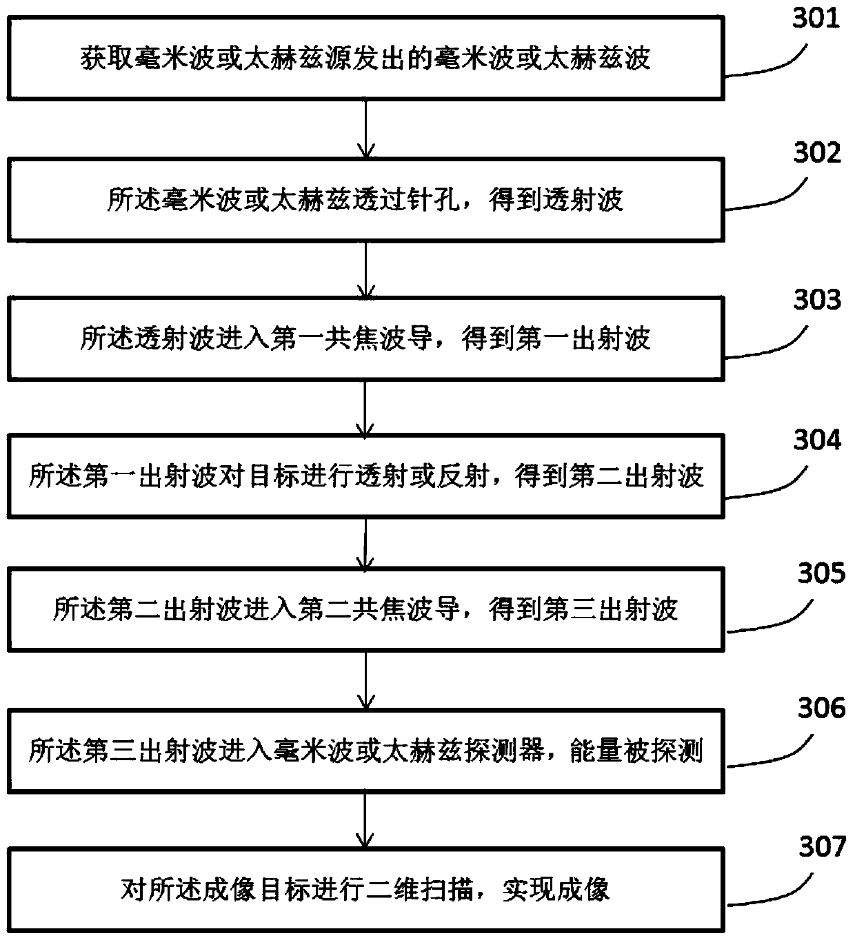
[0038] figure 1 This is a structural block diagram of a confocal waveguide terahertz imaging system according to an embodiment of the present invention. like figure 1 As shown, a conf...


PUM


Abstract

The invention discloses a terahertz super-resolution imaging system and method based on a confocal waveguide. The system comprises a terahertz or millimeter wave source, a pinhole, the confocal waveguide, an imaging target, a two-dimensional scanning mechanism, a second waveguide body and a detector. The terahertz or millimeter wave source is used for giving out a terahertz or millimeter wave; thepinhole is formed in an incident light path of the source and used for obtaining terahertz or millimeter transmission light; the confocal waveguide is composed of two confocal waveguide bodies, wherein the first waveguide body is arranged on an incident light path after the terahertz or millimeter wave transmits the pinhole and used for transmitting and focusing the terahertz or millimeter wave;the imaging target is arranged on the focal position of the first waveguide body; the two-dimensional scanning mechanism is used for controlling the imaging target to conduct scanning imaging; the second waveguide body is arranged on a transmission or reflection light path of the imaging target and used for transmitting and focusing a transmission wave; the detector is arranged on the focal position of the second waveguide body and used for detecting the intensity of the terahertz or millimeter wave, and finally imaging is achieved. According to the system, the confocal waveguide is used for replacing a traditional confocal lens to achieve focal imaging, the transmission loss of the terahertz or millimeter wave is reduced, the diffraction limit can be broken through, and super-resolution imaging is achieved.

Description

technical field [0001] The invention relates to the field of terahertz and millimeter wave super-resolution imaging, in particular to a terahertz super-resolution imaging system and method based on a confocal waveguide. Background technique [0002] High-resolution and high-quality terahertz or millimeter-wave imaging has become a very promising technology in the field of imaging due to its see-through and safety and non-destructive properties. in the fields of medicine, etc. As early as 1995, someone reported the terahertz imaging technology based on the terahertz time-domain spectroscopy system. Since then, various terahertz imaging technologies have been proposed, including: area array real-time imaging technology, near-field imaging technology, polarization imaging, common Focus imaging technology, etc. Compared with other imaging techniques, the principle of confocal imaging was first proposed by Minsky in 1955 and applied to imaging in the optical waveband. Because ...

Claims


Application Information

Patent Timeline
IPC IPC(8): G02B27/58G02B21/00
CPCG02B27/58G02B21/0032G02B21/0036
Inventor 龚诚
Owner 龚诚
Learn More