
Micronano optical fiber array coherent beam synthesizing device

A technology of micro-nano optical fiber and composite device, which is applied in the coupling of beam optical fibers, optical waveguides, optics, etc., can solve the problems of difficult to achieve rapid beam deflection and precise control.

Inactive Publication Date: 2007-11-14
ZHEJIANG UNIV
View PDF0 Cites 5 Cited by
  • Summary
  • Abstract
  • Description
  • Claims
  • Application Information

AI Technical Summary

Problems solved by technology

This method is difficult to achieve fast deflection and precise control of the beam

Method used


Image

  • Micronano optical fiber array coherent beam synthesizing device

Examples


Embodiment Construction

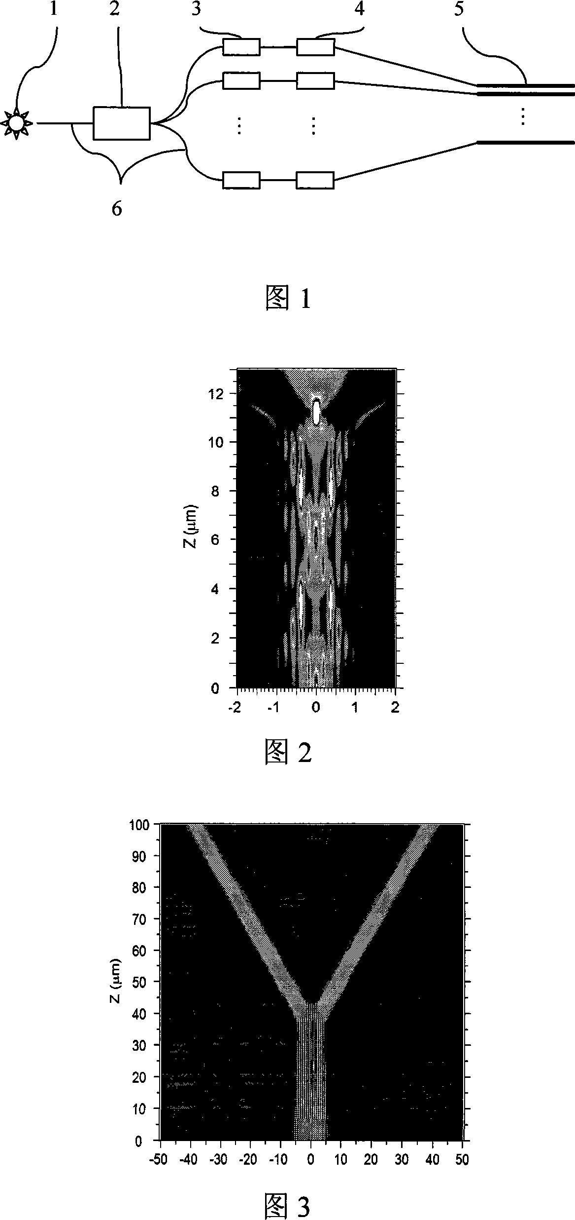
[0011] As shown in Figure 1, the micro-nano fiber array coherent beam combining device includes a light source 1, an optical beam splitter 2, a light intensity modulator 3, a phase modulator 4, a micro-nano fiber array 5, and an optical fiber 6. The light source 1 generates a coherent Light, through the optical beam splitter 2 to generate multiple beams of light, each beam is modulated by the light intensity modulator 3 and phase modulated by the phase modulator 4, and the modulated multiple beams are input to the micro-nano fiber array 5 In the process, the super mode is formed through the mode coupling between the micro-nano fibers, and finally the synthesized light beam is output from the end face of the micro-nano fiber array, and the above parts are connected by the optical fiber 6 .

[0012] The light source 1 is a laser. The micro-nano optical fiber array 5 is an array formed by a plurality of micro-nano optical fibers arranged in parallel at intervals. Micro-nano opti...


PUM


Abstract

The invention discloses micro-nano fiber array coherent beam devices. It includes the light source, optical beam splitter, optical stressed system, phase modulation, micro-nano fiber arrays, optical fiber. Light source produced a bouquet , through optical beam get a number of light beam, after each beam light stressed that the system of light-phase modulation and phase-modulation, the modulation of the beam input to a number of micro-nano fiber array, the micro-nano mode fiber coupling between a super-model, from the micro-final end satisfied that the output fiber array of beams, above all in part through fiber optic connectivity from. The invention can be achieved and subwavelength focusing collimated beam deflection and has control. In the realization of the focused beam direct-write laser lithography, optical storage, as well as biological cells in the laser operation has an important application. Implementation of the collimator and beam deflection of the beam be controlled optical switches, optical fiber communications, and has an important application.

Description

technical field [0001] The invention relates to a coherent beam combining device, in particular to a micro-nano fiber array coherent beam combining device. Background technique [0002] For a long time, due to the limitation of the light wave diffraction limit, it is difficult to reduce the focused spot of the beam below the wavelength scale, which restricts the further development of optical storage, lithography and other technologies. In order to obtain a smaller focused spot, there are two possible technical approaches: one is to increase the numerical aperture of the focusing lens under the condition of light wave diffraction limit, this method is limited by the material, processing technology and geometric size of the optical system It is difficult to further reduce the diameter of the focused spot; another method is to use the artificial electromagnetic material with negative refraction effect to break through the diffraction limit of light waves, but it is difficult t...

Claims


Application Information

Patent Timeline
IPC IPC(8): G02B6/26G02B6/28G02B6/04G02F1/01
Inventor 符建童利民刘旭
Owner ZHEJIANG UNIV
Learn More