
Ultra-thin plano-concave lens realizing subwavelength focusing

A plano-concave lens and subwavelength technology, which is applied in the field of simulation design of subwavelength focusing lenses in the mid-infrared band, can solve the problems of large curvature of super lens and inability to achieve far-field focusing, and achieves good electromagnetic compatibility, integration and small size. the effect of reducing the quality and size of

Active Publication Date: 2016-11-16
BEIJING RES INST OF SPATIAL MECHANICAL & ELECTRICAL TECH
View PDF1 Cites 4 Cited by
  • Summary
  • Abstract
  • Description
  • Claims
  • Application Information

AI Technical Summary

Problems solved by technology

[0004] The technical problem solved by the present invention is: to overcome the deficiencies of the prior art, provide an ultra-thin plano-concave lens that can realize far-field sub-wavelength focusing, and solve the problems that the original super lens has a large curvature and cannot realize far-field focusing

Method used


Image

  • Ultra-thin plano-concave lens realizing subwavelength focusing
  • Ultra-thin plano-concave lens realizing subwavelength focusing
  • Ultra-thin plano-concave lens realizing subwavelength focusing

Examples


Embodiment Construction

[0015] High-frequency evanescent waves cannot propagate in conventional materials, mainly because of the physical bottleneck of truncated wave vectors. By constructing a material system with different signs of radial and tangential dielectric constants, evanescent wave propagation and sub-wavelength focused imaging Foundation.

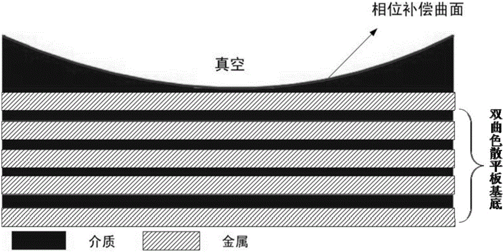
[0016] Such as figure 1 As shown, the ultra-thin plano-concave lens consists of two parts: a concave ultra-thin dielectric film structure and a hyperbolic dispersion plate substrate. Constants with different signs. In this model, the specific form of "concave surface" such as the shape of the curve is limited by the refractive index, focal length, object distance, dielectric constant and related geometric dimensions of the concave ultra-thin dielectric film and the hyperbolic dispersion plate substrate. We call this curve shape formula is the optical transfer function.

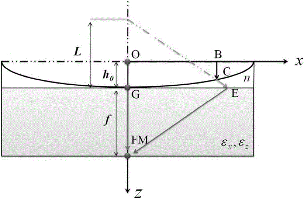
[0017] Next, the optical transfer function of the plano-concave thin lens is sp...


PUM


Abstract

The invention provides an ultra-thin plano-concave lens realizing subwavelength focusing. The ultra-thin plano-concave lens comprises a concave ultra-thin dielectric film structure and a hyperbolic dispersion flat substrate. The hyperbolic dispersion flat substrate consists of a dielectric and a metal multilayer film. A tangential dielectric constant and a radial dielectric constant are contrary signs. The concave ultra-thin dielectric film and the dielectric of the substrate are made of the same material. The concave shape follows an optical transfer function formula. According to the invention, a lens model which integrates a concave surface phase compensation mechanism and the hyperbolic dispersion flat substrate is provided for the first time; compared with a hemispherical super-lens, the ultra-thin plano-concave lens has an added concave super-thin dielectric film on the flat substrate; the quality and the size of the lens are greatly reduced; the problem that a traditional super-lens cannot carry out far-field imaging is solved; and integration and miniaturization of an optical system are realized.

Description

technical field [0001] The invention belongs to the technical field of optical imaging and relates to the simulation design of a mid-infrared band sub-wavelength focusing lens. Background technique [0002] For a long time, people have always believed that the diffraction limit proposed by the German scientist Ernst Abbe is an insurmountable mountain in the lens imaging process. No matter how the lens manufacturing process is improved, the smallest structure that can be resolved by the lens will eventually be frozen to the size of half a wavelength. The so-called diffraction pole means that when an ideal point is imaged by the optical system, due to the limitation of diffraction, it is impossible to obtain an ideal image point but a Fraunhofer diffraction image centered on the image point. For general optical lenses, the aperture is basically circular, so that the imaging of each object point is a diffuse spot, and the two diffuse spots will become indistinguishable when the...

Claims


Application Information

Patent Timeline
Patent Type & Authority Applications(China)
IPC IPC(8): G02B3/00G02B27/00
CPCG02B3/00G02B27/0012
Inventor 孙倩阮宁娟
Owner BEIJING RES INST OF SPATIAL MECHANICAL & ELECTRICAL TECH
Learn More