
Remote photoelectric switching network server capable of freely expanding space

A network server and remote technology, which is applied in the field of remote photoelectric switching network servers, can solve the problems of destroying the overall aesthetics, the number of cooling ports, and poor cooling effects, so as to avoid bad interfaces, improve the overall aesthetics, and avoid slipping Effect

Pending Publication Date: 2019-04-26
王佩洁
View PDF4 Cites 0 Cited by
  • Summary
  • Abstract
  • Description
  • Claims
  • Application Information

AI Technical Summary

Problems solved by technology

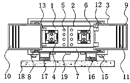
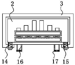
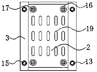
[0005] Aiming at the deficiencies of the prior art, the present invention provides a remote photoelectric switching network server that can freely expand the space, which solves the problem that the ventilation and heat dissipation vents of the existing photoelectric switching network server proposed in the above-mentioned background technology are mainly arranged on the main casing and the cover. On the side of the board, due to the small side area of ​​the photoelectric switch network server, the number of heat dissipation ports is relatively small, resulting in slow heat dissipation and poor heat dissipation effect. Secondly, the general photoelectric switch network server is connected to the shell by screws. Problems where the screws sit on the surface of the device and detract from its overall aesthetics

Method used


Image

  • Remote photoelectric switching network server capable of freely expanding space
  • Remote photoelectric switching network server capable of freely expanding space
  • Remote photoelectric switching network server capable of freely expanding space

Examples


Embodiment Construction

[0027] The following will clearly and completely describe the technical solutions in the embodiments of the present invention with reference to the accompanying drawings in the embodiments of the present invention. Obviously, the described embodiments are only some, not all, embodiments of the present invention.

[0028] In the description of the present invention, unless otherwise stated, the meaning of "plurality" is two or more; the terms "upper", "lower", "left", "right", "inner", "outer" , "front end", "rear end", "head", "tail", etc. indicate the orientation or positional relationship based on the orientation or positional relationship shown in the drawings, and are only for the convenience of describing the present invention and simplifying the description, rather than Nothing indicating or implying that a referenced device or element must have a particular orientation, be constructed, and operate in a particular orientation should therefore not be construed as limiting ...


PUM


Abstract

The invention discloses a remote photoelectric switching network server capable of freely expanding space, relating to the technical field of network devices. Specifically, the remote photoelectric switching network server comprises a hundred trillion photoelectric transceiver and support legs, wherein the hundred trillion photoelectric transceiver comprises a main enclosure and a cover plate, thefront end of the main enclosure is provided with a first interface, an LED indicator lamp, a second interface and slide rails, the second interface is arranged on the right of the LED indicator lamp,slide rails are arranged at upper and lower edges of the front end of the main enclosure, and the upper ends of the support legs and the lower surface of the main enclosure are welded. Due to arrangement of a first protective board and a second protective board, the device can cover the first interface and the second interface, thereby further protecting the first interface and the second interface from dust and water; in addition, fixed bolts of the device are at the lower ends of the cover plate and the main enclosure, so that when the device is horizontally placed, the fixed bolts cannot be seen directly, and the overall appearance of the device is more attractive.

Description

technical field [0001] The invention relates to the technical field of network equipment, in particular to a remote photoelectric switching network server that can freely develop space. Background technique [0002] The photoelectric converter is a device similar to the baseband MODEM (digital modem). The difference from the baseband MODEM is that it is connected to an optical fiber dedicated line, which is an optical signal. It is divided into full-duplex flow control, half-duplex back pressure control, photoelectric Converters (also known as fiber optic transceivers) are divided into 100M fiber optic transceivers and Gigabit fiber optic transceivers. It is a fast Ethernet with a data transmission rate of 1Gbps. The existing Ethernet is compatible. With the support of the wiring system, the original Fast Ethernet can be upgraded smoothly and the original investment of the user can be fully protected. Gigabit network technology has become the preferred technology for new net...

Claims


Application Information

Patent Timeline
Patent Type & Authority Applications(China)
IPC IPC(8): H04L12/28H04Q1/08H04Q1/02
CPCH04L12/2856H04Q1/02H04Q1/035H04Q1/08
Inventor 王佩洁
Owner 王佩洁
Learn More