
Steel bar spraying equipment for wave-type anti-stirring bridge

A technology for spraying equipment and bridges. It is applied in the direction of spraying devices, etc. It can solve problems such as rusting and corrosion on the surface of steel bars, rust and corrosion on the surface of steel bars, and affect the color, so as to avoid large-area film formation or agglomeration.

Inactive Publication Date: 2019-04-30
潘晓青
View PDF5 Cites 2 Cited by
  • Summary
  • Abstract
  • Description
  • Claims
  • Application Information

AI Technical Summary

Problems solved by technology

[0003] Aiming at the deficiencies in the prior art, the object of the present invention is to provide a wave-type anti-stirring bridge steel bar spraying equipment to solve the problem of the paint storage barrel of the spraying equipment in the prior art during the use of paint. Long-term storage, under the action of its own conditions, it is easy to form a layer of film or accumulate particles on the inner wall of the barrel, which will cause the two paints to mix together when using different paints next time, affecting the color. The stirring is clockwise or counterclockwise. When the paint is in use, there will still be most of the air bubbles, which will make the surface of the steel bar after painting have many bumps. After the paint is dry, the surface of the steel bar will easily appear dots Rust Corrosion Defects

Method used


Image

  • Steel bar spraying equipment for wave-type anti-stirring bridge
  • Steel bar spraying equipment for wave-type anti-stirring bridge
  • Steel bar spraying equipment for wave-type anti-stirring bridge

Examples


Embodiment Construction

[0023] In order to make the technical means, creative features, goals and effects achieved by the present invention easy to understand, the present invention will be further described below in conjunction with specific embodiments.

[0024] Such as Figure 1-Figure 4 As shown, the present invention provides a kind of technical scheme of steel bar spraying equipment for wave type anti-stirring bridge:

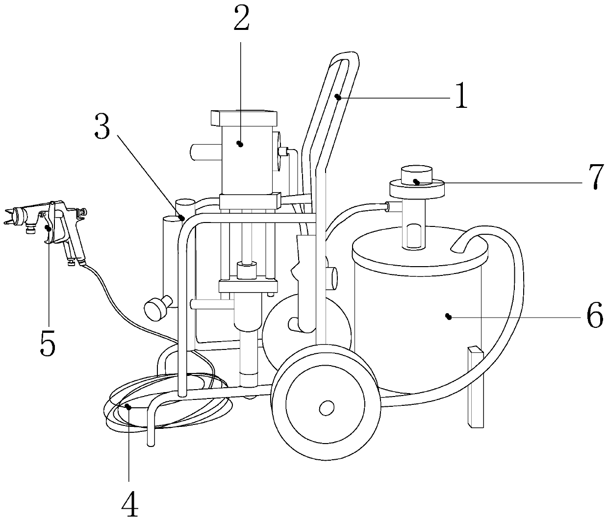
[0025] Such as Figure 1-Figure 2 Shown, a kind of wave-type anti-stirring bridge steel bar spraying equipment, its structure comprises trolley 1, air compressor 2, filter regulator 3, air pipe 4, spray gun 5, material storage tank 6, pneumatic mixer 7, described The air compressor 2 is installed in the middle of the cart 1 and connected by electric welding, the filter regulator 3 is electrically connected to the air compressor 2, the storage tank 6 is installed on the right side of the cart 1, and the storage tank 6 is connected to the spray gun 5 through the air pipe 4, the ...


PUM


Abstract

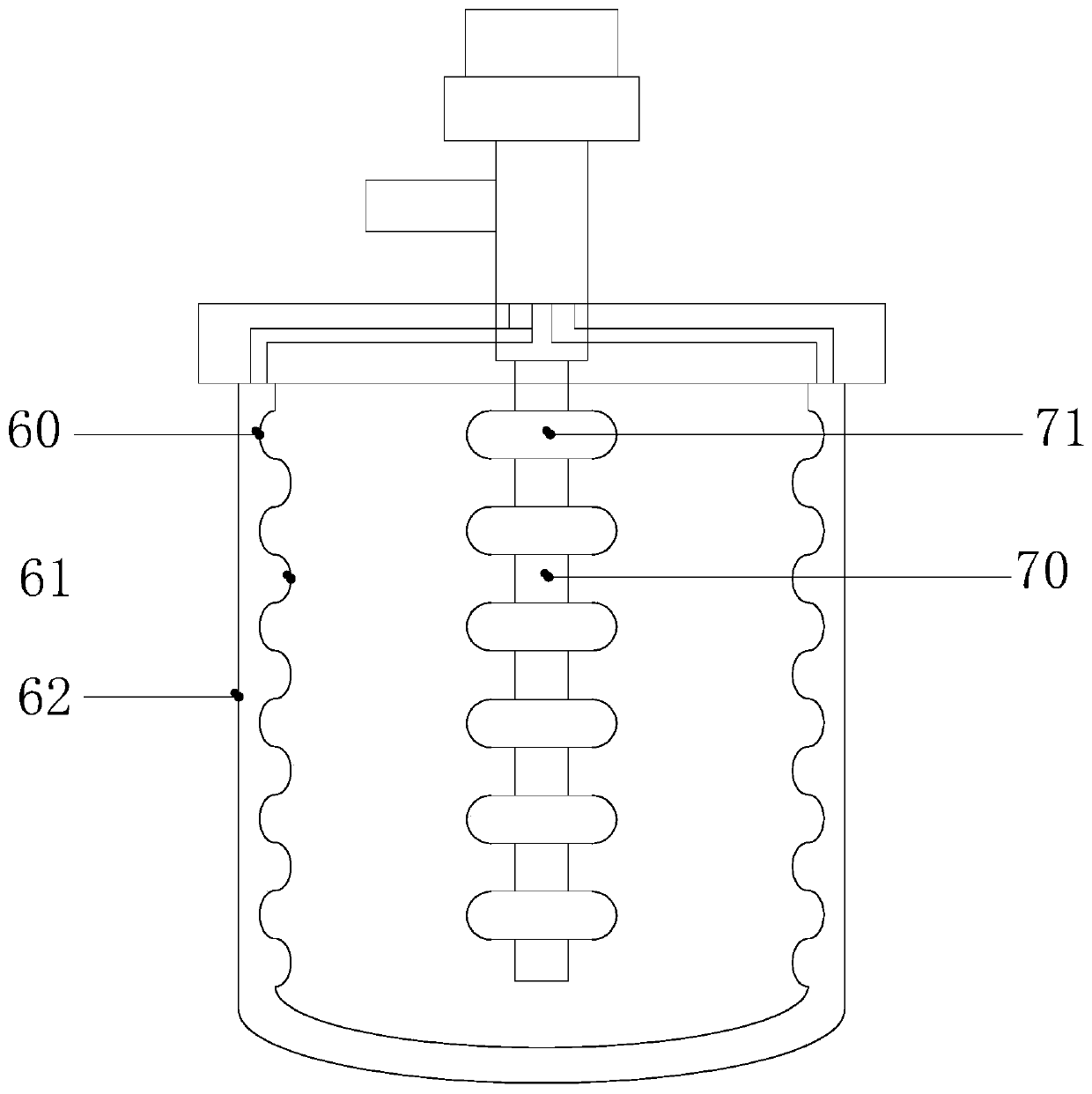
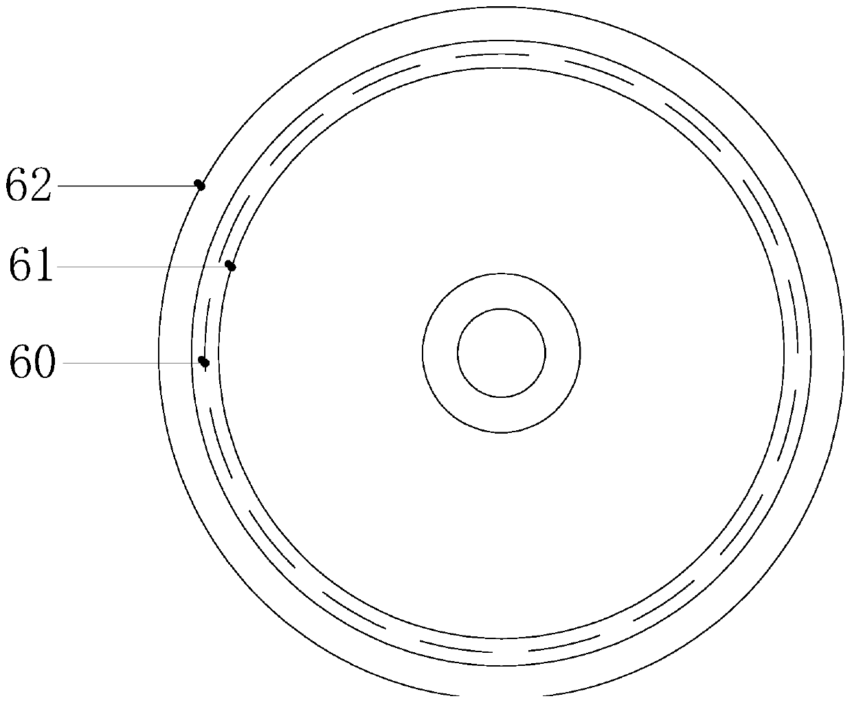
The invention discloses steel bar spraying equipment for a wave-type anti-stirring bridge. The steel bar spraying equipment structurally comprises a trolley, an air compressor, a filter pressure stabilizer, an air pipe, a spray gun, a material storage barrel and a pneumatic stirrer. The steel bar spraying equipment has the beneficial effects that a wave structure composed of an auxiliary anti-stirring mechanism and an anti-sticking plate is utilized to enable paint of the barrel wall to be quickly dropped under the action of gravity in the use process of the paint, so that the phenomenon thata paint film or caking occurs on the wall of the barrel wall in a large area is avoided; the auxiliary anti-stirring mechanism is used for intensively blowing the oil paint into the center of the barrel in parallel, an inner concave arc-shaped plate and a flat round-shaped body are located on the same horizontal line, and when the paint touches the flat round body under the action of air pressure,the paint is scattered to the two sides to be reversely stirred so as to reduce the bubbles inside the paint; and the rotation of a pneumatic stirrer and the horizontal line of the auxiliary anti-stirring mechanism are utilized, so that the oil paint is mixed and stirred under the cooperation of two strands of force, the paint is more uniform, and the air pressure generated by the auxiliary anti-stirring mechanism enables the oil paint to diffuse towards two sides to reduce air bubbles inside the paint when the paint touches the flat round body.

Description

technical field [0001] The invention relates to the field of spraying equipment, more precisely, it relates to a steel bar spraying equipment for wave-type anti-stirring bridges. Background technique [0002] Bridges are generally erected on rivers, lakes, and seas. They usually need to be installed with arched or other shaped steel bars for safety protection. Because of the large demand for steel bars, they need to be painted before they can be installed. However, during transportation During the process, some of the steel bars have paint falling off due to bumping. At this time, it is necessary to use movable spraying equipment to repair the paint to prevent the steel bars from rusting and corrosion. During use, due to the long-term storage of the paint, it is easy to form a film or accumulate particles on the inner wall of the barrel under its own conditions, which will cause the two paints to mix together when using different paints next time, affecting the color. At th...

Claims


Application Information

Patent Timeline
IPC IPC(8): B05B15/25B05B15/00
CPCB05B15/00B05B15/25
Inventor 潘晓青
Owner 潘晓青
Learn More