Crawling robot top cover screw locking device matched with rotary type vehicle

A screw-locking and rotating technology, which is applied in the field of screw-locking devices on the top cover of crawling robots, can solve the problems of lower production costs, low production efficiency, and cumbersome positioning, and achieve the goals of reducing energy consumption, convenient positioning, and reducing the number of up and down lifts Effect

Active Publication Date: 2019-04-30
江苏大盛铁塔制造有限公司
View PDF10 Cites 3 Cited by
  • Summary
  • Abstract
  • Description
  • Claims
  • Application Information

AI Technical Summary

Problems solved by technology

[0007] At present, the screwing operation of the product is mostly done manually or by a single-axis screw machine; when it is done manually, the worker holds an electric screwdriver or an air screwdriver, and manually puts the screw into the screw hole before proceeding. Locking operation, obviously, such an operation is complicated and inefficient. When a single-axis screw machine is used, the electric screwdriver or air screwdriver needs to repeatedly move between multiple screw holes. As far as the product is concerned, the production efficiency is also low, which is not conducive to reducing production costs. At the same time, the positioning is cumbersome and prone to large errors when screwing each time.

Method used


Image

  • Crawling robot top cover screw locking device matched with rotary type vehicle
  • Crawling robot top cover screw locking device matched with rotary type vehicle
  • Crawling robot top cover screw locking device matched with rotary type vehicle

Examples


Embodiment Construction

[0036] In order to enable those skilled in the art to better understand the technical solution of the present invention, the present invention will be described in detail below in conjunction with the accompanying drawings. The description in this part is only exemplary and explanatory, and should not have any limiting effect on the protection scope of the present invention. .

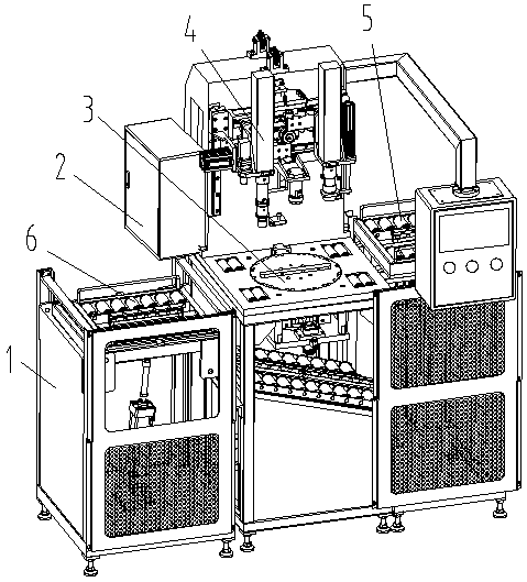
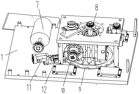
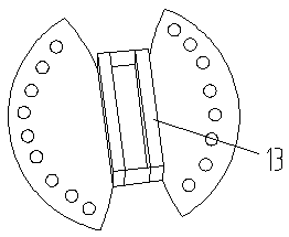
[0037] Such as Figure 1-Figure 7As shown, the specific structure of the present invention is: a crawling robot top cover locking screw device matched with a rotary carrier, which includes a frame 1 and a power distribution control box 2, and the frame 1 is provided with a loading Device 3, the loading device 3 is equipped with a locking screw device 4, the loading device 3 includes a turntable motor 7 and a turntable shaft 8 that are arranged on the frame 1 and cooperate with each other, and the turntable shaft 8 is A turntable 9 is provided, the upper part of the turntable 9 is provided with a protr...


PUM


Abstract

The invention relates to a crawling robot top cover screw locking device matched with a rotary type vehicle. The crawling robot top cover screw locking device comprises a machine frame and a power distribution control box, wherein a material loading device is arranged on the machine frame, and a screw locking device is matched with the material loading device; the material loading device comprisesa rotating disk motor and a rotating disk rotating shaft, wherein the rotating disk motor and the rotating disk rotating shaft are mutually matched, and a rotating disk is arranged on the rotating disk rotating shaft; a raised block matched with a matching groove of a top cover is arranged on the upper part of the rotating disk, and rotating disk clamping teeth are uniformly arranged on the lowerpart of the rotating disk; and a rotating disk position clamping air cylinder is arranged on the machine frame, and a rotating disk position clamping block matched with the rotating disk clamping teeth is connected to the rotating disk position clamping air cylinder. According to the crawling robot top cover screw locking device matched with the rotary type vehicle, the rotating disk is adopted and used for material loading of the top cover, and the raised block matched with the matching groove of the top cover is arranged on the rotating disk, it is ensured that the top cover cannot rotate relative to the rotating disk when the top cover rotates, the screw locking device does not need to be moved, the positioning is convenient, the screw locking efficiency is high, and the low-cost production can be realized.

Description

[0001] Original application number: 2017100025799 [0002] Applicant of the original case: Dongguan Institute of Technology [0003] Date of original filing: January 3, 2017 [0004] The name of the original application: a crawling robot top cover rotary locking screw machine. technical field [0005] The invention relates to the field of processing parts of a crawling robot, in particular to a top cover locking screw device of a crawling robot matched with a rotary carrier. Background technique [0006] With the advancement of mechanization, all walks of life have adopted robots for operations, especially in the field of climbing, most of which will use crawling robots for operations. Most crawling robots will be equipped with a top cover, most of which are as image 3 As shown, there is a matching groove, and there are multiple sets of threaded holes symmetrically arranged on the cover plate, and screws and female nails need to be driven into the threaded holes. [0007]...

Claims


Application Information

Patent Timeline
Patent Type & Authority Applications(China)
IPC IPC(8): B23P19/06
CPCB23P19/001B23P19/06
Inventor 邓君
Owner 江苏大盛铁塔制造有限公司
Why Eureka
Try Eureka