Material binding device for industrial design

A technology of industrial design and support table, which is applied in binding and other directions, can solve the problems of inability to achieve the binding effect, cumbersome operation of the binding machine, and affect the binding effect, and achieve the effects of novel design, increased binding quality, and strong practicability

Inactive Publication Date: 2019-04-30
李瑞
View PDF5 Cites 11 Cited by
  • Summary
  • Abstract
  • Description
  • Claims
  • Application Information

AI Technical Summary

Problems solved by technology

[0003] When putting industrial design materials into the cabinet, it is generally necessary to bind both of them to avoid omissions. Therefore, voucher binding is an essential part, but the operation of general binding machines is too cumbersome and cannot achieve good binding. effect, resulting in time-consuming and labor-intensive labor-intensive
[0004] Chinese patent (publication number: CN108790455A) discloses a material binding device for industrial design, including a first base, a second base, a connecting plate, a first column, a second column, a first buffer seat, a first bolt, a second A briquetting block, a first bearing, a first handle, a third column, a fourth column, a second buffer seat, a second bolt, a second briquetting block, a second bearing, a second handle, a casing, a lead screw, a drive motor and Binding head, although this device can realize the binding of multiple materials to a certain extent, but in actual binding, the device squeezes and fixes the materials through the pressure plates at both ends. Protrusion or depression will seriously affect the post-binding effect, so it needs to be improved

Method used


Image

  • Material binding device for industrial design
  • Material binding device for industrial design
  • Material binding device for industrial design

Examples


Embodiment 1

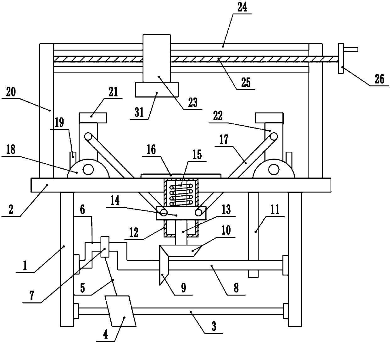
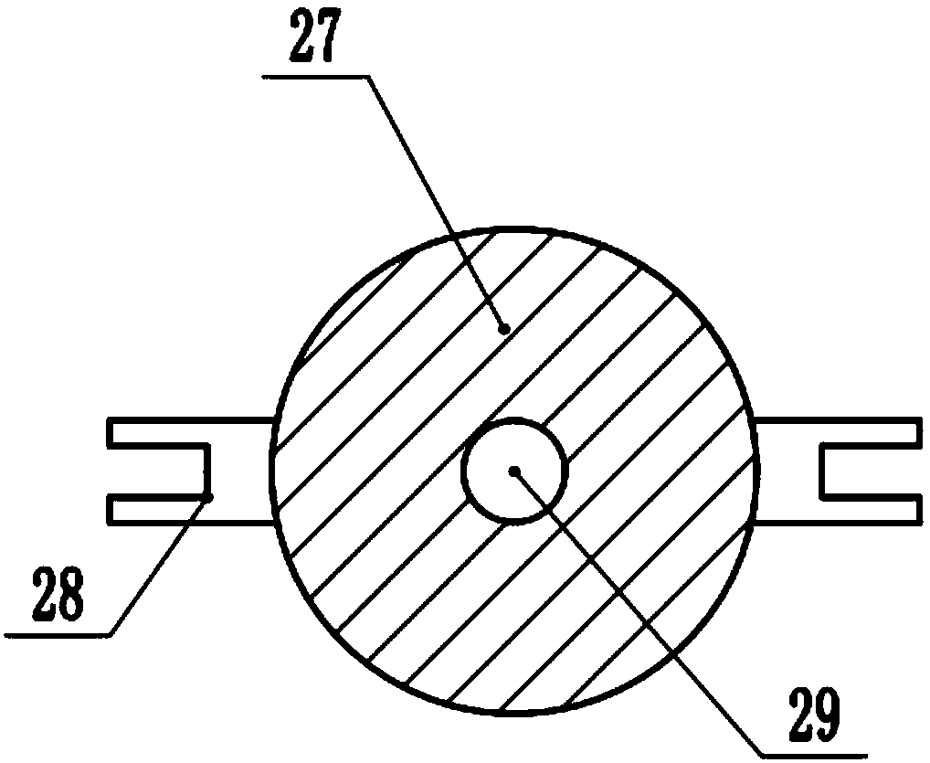
[0027] refer to figure 1 , in an embodiment of the present invention, a material binding device for industrial design, comprising a support leg 1 and a support table 2 fixed to the upper end of the support leg 1, a binding table 16 is installed in the middle of the upper end of the support table 2, for placing Industrial design material, a rotating shaft 8 is installed between the supporting legs 1, and a limit frame 11 is installed in the middle of the right end of the rotating shaft 8, which is used to limit the rotation of the rotating shaft 8 and avoid shaking during its rotation , and then ensure the accurate meshing between the driving gear 9 and the driven gear 10, the limit frame 11 is fixed on the right side of the lower end of the support table 2, the driving gear 9 is installed in the middle of the rotating shaft 8, and the middle part of the left end of the rotating shaft 8 is installed Crank 6, the middle part of crank 6 is equipped with sliding sleeve 7, and slid...

Embodiment 2

[0031] In another embodiment of the present invention, the difference between this embodiment and the above-mentioned embodiment is that stoppers 19 are installed on both ends of the fixed block 18, and the rotation angle of the fixed block 18 is limited by setting the stoppers 19, Further ensure device reliability.

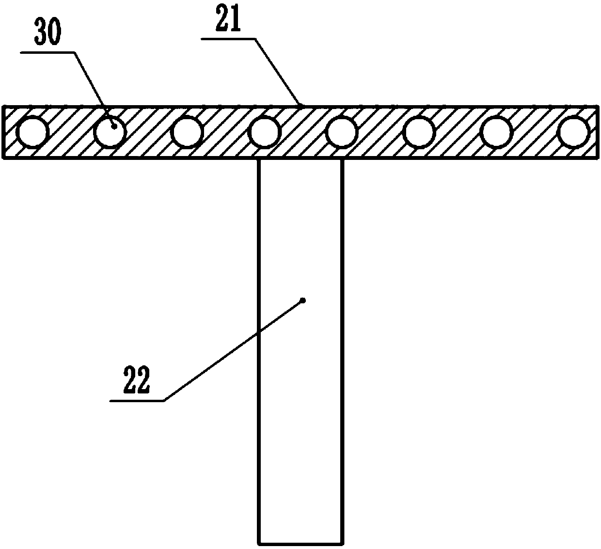
[0032]In the present invention, when working, put the materials that need to be bound on the binding table 16 after sorting out, then step on the pedal 4 to rotate, so that the rotating shaft 8 rotates, and then the driving gear 9 and the driven gear 10 are meshed with the screw mandrel 13 Rotate to make the lifting mechanism 14 move down, and then make the action of the pull rod 17, so that the rotating rod 22 drives the clamping block 21 to move down, and the edge of the industrial design material is clamped and fixed, and then the rotating handle 26 is turned to make the screw 25 is rotated so that the guide block 23 drives the binding head 31 to move to a cor...


PUM


Abstract

The invention discloses a material binding device for industrial design, and belongs to the technical field of industrial design. The material binding device for the industrial design comprises supporting legs and a supporting platform fixed at the upper ends of the supporting legs, a rotating shaft is installed between the supporting legs, a driving gear is installed in the middle of the rotatingshaft, a crank is installed in the middle of the left end of the rotating shaft, a sliding sleeve is installed in the middle of the crank, the sliding sleeve is connected with a pedal through a connecting rod, a fixing barrel is installed in the middle of the supporting platform, a lead screw is installed in the fixing barrel, a lifting mechanism is installed in the middle of the lead screw through an inner threaded hole, rotating rods are connected to the two ends of the lifting mechanism through pulling rods, pressing blocks are fixed to the top ends of the rotating rods, the bottom ends ofthe rotating rods are connected with fixing blocks in a hinged mode, the fixing blocks are fixed to the two sides of the upper end of the supporting platform, and the bottom end of the lead screw penetrates through the fixing barrel and is connected with the driving gear. According to the material binding device for industrial design, efficient fixing to the industrial design material is realized, protrusion or sinking in the binding process are avoided, the binding quality is increased, only hand and foot force is needed in the binding process, and the operation is easy.

Description

technical field [0001] The invention relates to the technical field of industrial design, in particular to a material binding device for industrial design. Background technique [0002] Industrial design, referred to as ID. It refers to the design of industrial products based on engineering, aesthetics and economics. Industrial design is divided into four categories: product design, environmental design, communication design, and design management; including modeling design, mechanical design, circuit design, clothing design, environmental planning, interior design, architectural design, UI design, graphic design, packaging design, advertising design, animation design, display design, website design, etc. Industrial design, also known as industrial product design, involves psychology, sociology, aesthetics, ergonomics, mechanical structure, photography, color science, etc. Industrial design brought about by industrial development and division of labor is obviously differe...

Claims


Application Information

Patent Timeline
Patent Type & Authority Applications(China)
IPC IPC(8): B42B5/02
Inventor 李瑞
Owner 李瑞
Why Eureka
Try Eureka