
Heating ring die system for straw biomass granulator

A biomass pellet and heating ring technology, which is applied in the fields of biofuels, heating devices, lighting and heating equipment, etc., can solve the problem of 10-20 minutes for machine preparation, and the same time required for shutdown, increasing production costs and pelletizing time. It can improve the adaptability of raw materials, improve work efficiency, and prevent production accidents.

Pending Publication Date: 2019-04-30
庞中化
View PDF7 Cites 2 Cited by
  • Summary
  • Abstract
  • Description
  • Claims
  • Application Information

AI Technical Summary

Problems solved by technology

The biofuel made of straw is environmentally friendly and pollution-free. The biomass pellet machine is an important tool for processing straw into biomass fuel. On average, it takes 10-20 minutes for a machine to prepare for water material, oil material or wet water material, and it also takes this time to shut down, resulting in long granulation time and low efficiency
In addition, it is difficult for conventional granulators to press and shape raw materials with more than 20% moisture
Conventional practice is either to dry the ingredients, thus wasting a lot of time
Either add a drying equipment, which will greatly increase the production cost

Method used


Image

  • Heating ring die system for straw biomass granulator
  • Heating ring die system for straw biomass granulator
  • Heating ring die system for straw biomass granulator

Examples


Embodiment 1

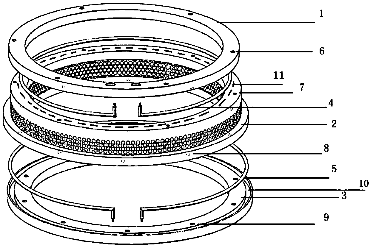
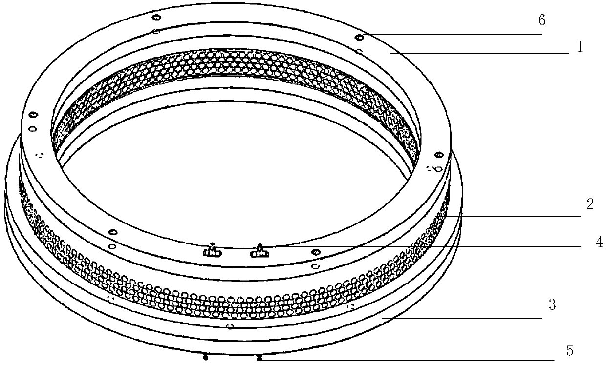
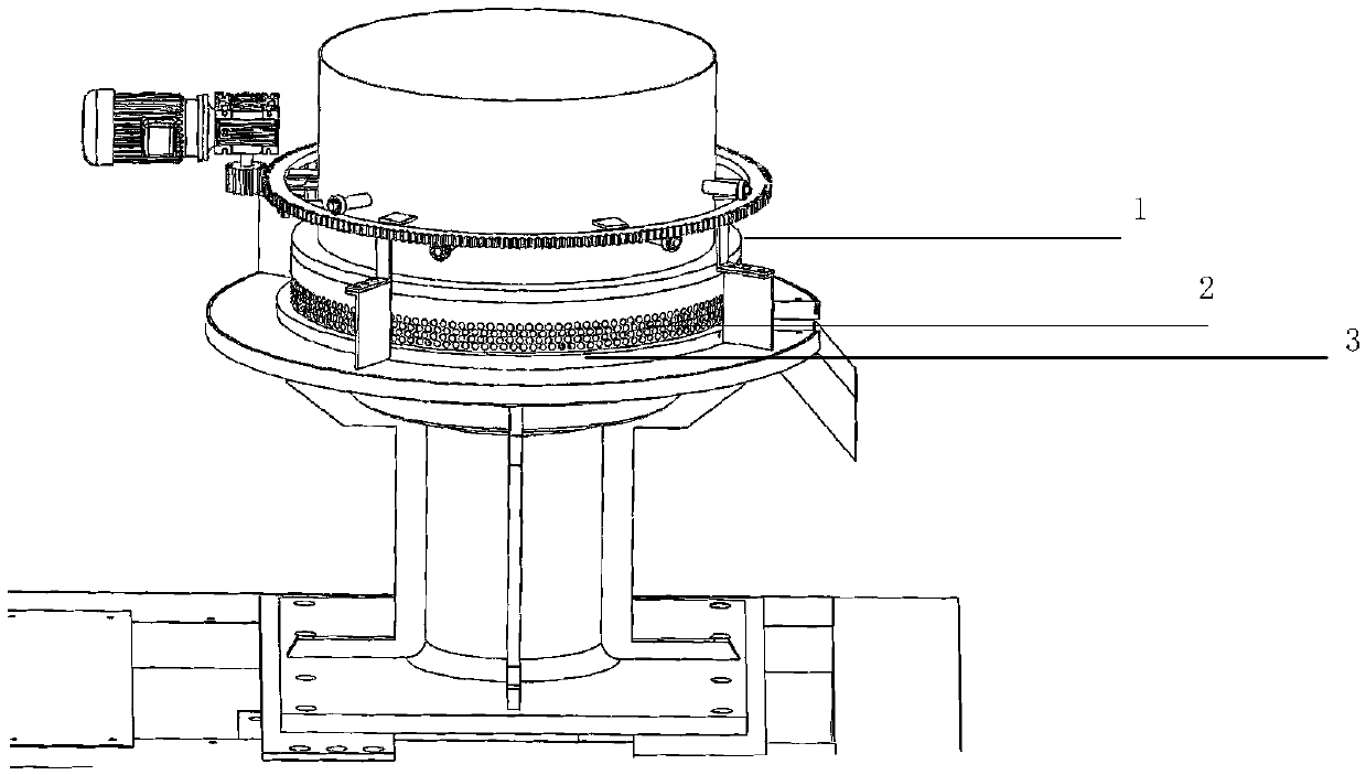
[0019] In order to make the technical solution and advantages of the device of the present invention clearer, the present invention will be further described in detail below in conjunction with the accompanying drawings through specific implementation methods. It should be particularly pointed out that the specific implementations described in this specification are only used to explain the device of the present invention, rather than to limit the present invention. see figure 1 , figure 2 , this embodiment 1 discloses a heating device for the ring die of a straw biomass pellet machine, including a compression flange 1, a ring die 2, a bottom plate 3 of the ring die, an upper heating element 4 located on the upper part of the ring die, and an upper heating element 4 located on the ring die 2 The lower heating element 5 below, the ring die 2 and the ring die bottom plate 3 are respectively provided with an upper groove 11 accommodating the upper heating element and a lower gr...

Embodiment 2

[0022] Similar to Embodiment 1, the difference lies in the number and position of the heating elements. In this embodiment, the heating ring mold system device only has the upper heating element 4, and the upper part of the ring mold 2 is provided with a groove for accommodating the upper heating element 4 11,6 is the through hole of the upper fastening bolt, and 7 is the corresponding upper fixing hole with internal thread. Fastening bolts tightly seal the upper heating element 4 in the upper groove 11 through a plurality of through holes 6 evenly distributed on the compression flange and correspondingly distributed on the ring die 2 with internal thread fixing holes 7, leaving only the electrode It is electrically connected with the power supply for heating. In this embodiment, the upper heating element 4 adopts a ring-shaped electric heating rod, and the ring-shaped electric heating rod coincides with the axes of the compression flange 1 , the ring die 2 , and the bottom pl...

Embodiment 3

[0041] Similar to Embodiment 1, the difference lies in the number and position of the heating elements. In this embodiment, there is only the lower heating element 5, and a groove 10 for accommodating the lower heating element 5 is arranged above the bottom plate of the ring die, and 8 is the lower heating element 5. The fastening bolt through hole, 9 is the corresponding lower fixing hole with internal thread. The fastening bolts seal the lower heating element 5 tightly in the groove 10 through a plurality of through holes 8 evenly distributed on the ring die 2 and correspondingly distributed on the ring die bottom plate 3 with internal thread fixing holes 9, leaving only the electrodes and The heating is electrically connected to a power supply. In this embodiment, the lower heating element 5 adopts a ring-shaped electric heating rod, and the ring-shaped electric heating rod coincides with the axes of the compression flange 1 , the ring die 2 , and the bottom plate 3 of the ...


PUM


Abstract

The invention belongs to the field of biofuel manufacturing devices, and provides a special heating ring die system device for a biomass granulator to improve the production efficiency and increase the raw material adaptability of the biomass granulator. The system device sequentially includes a torus pressing flange, an upper heating element, a torus ring die, a lower heating element and a torusring die baseboard from top to bottom, the upper part of the ring die is provided with an upper groove for accommodating the upper heating element, the upper part of the ring die baseboard is providedwith a lower groove for accommodating the lower heating element, and the pressing flange, the upper heating element, the ring die, the lower heating element and the ring die baseboard are fixed by fastening bolts, through holes and fixing holes in order to make the upper heating element and the lower heating element respectively sealed in the upper groove and the lower groove and isolated from the outside. The upper heating element and the lower heating element adopt electric heating rods or PTC heating rods, and are closely attached to the pressing flange, the ring die and the ring mold baseboard to ensure good heat conduction. The granulator using the device does not need to be preheated for mixing, so the turn-on time is obviously saved.

Description

technical field [0001] The invention relates to biofuel manufacturing equipment, in particular to the field of a heating ring die system device of a straw biomass pellet machine. Background technique [0002] Biomass fuel refers to the burning of biomass materials as fuel, generally including straw, that is, the remaining parts of wheat, rice, corn, potatoes, rapeseed, cotton, sugarcane and other crops after harvesting seeds, and other agricultural and forestry wastes. . The biofuel made of straw is environmentally friendly and pollution-free. The biomass pellet machine is an important tool for processing straw into biomass fuel. On average, it takes 10-20 minutes for a machine to prepare for water feed, oil feed or wet water feed, and it also takes this time to shut down, resulting in long granulation time and low efficiency. In addition, it is difficult for conventional granulators to press and shape raw materials with more than 20% moisture. The conventional method is ...

Claims


Application Information

Patent Timeline
Patent Type & Authority Applications(China)
IPC IPC(8): C10L5/44B01J2/22F26B23/04
CPCB01J2/22F26B23/04C10L5/445C10L2290/32C10L2290/08Y02E50/10Y02E50/30
Inventor 庞中化
Owner 庞中化
Learn More