
Telescopic concrete pump pipe assembly

A technology of concrete pump pipe and telescopic pipe, which is applied in the direction of construction, building structure, and building material processing, etc., to achieve the effects of ensuring stability, high control precision, and simple structure

Pending Publication Date: 2019-04-30
中交四航局江门航通船业有限公司 +3
View PDF0 Cites 0 Cited by
  • Summary
  • Abstract
  • Description
  • Claims
  • Application Information

AI Technical Summary

Problems solved by technology

However, in the prior art, there is a lack of effective equipment to achieve this technical purpose. In view of this situation, the present invention designs a telescopic and controllable pipeline with adjustable height

Method used


Image

  • Telescopic concrete pump pipe assembly
  • Telescopic concrete pump pipe assembly
  • Telescopic concrete pump pipe assembly

Examples


Embodiment Construction

[0021] The present invention will be described in further detail below in conjunction with the accompanying drawings.

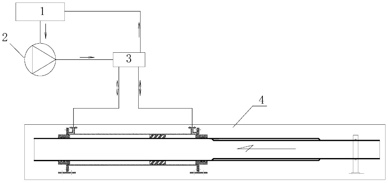
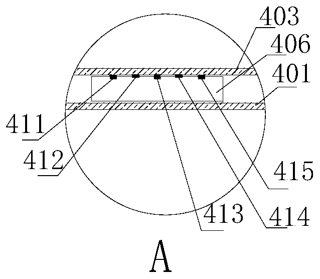
[0022] Such as figure 1 and figure 2 The telescopic concrete pump pipe integration of the present invention shown includes the original pipe 402, the telescopic pipe 401, the cylinder 403, the pump 2 and the pressure supply equipment (ie, the oil tank 1 in the figure).

[0023] The original pipe 402 is fixed on an external equipment support, or fixed relative to an external building, and the telescopic pipe 401 is movably fitted and socketed outside the original pipe 402 and can slide axially relative to the original pipe 402 . The outer wall of the end of the original pipe 402 is covered with a sealing ring 424 at the end of the original pipe to seal the gap between the original pipe 402 and the telescopic pipe 401 .

[0024] The outer wall of one section of the telescopic tube 401 is sleeved with a cylinder 403, and an annular chamber is formed between t...


PUM


Abstract

The invention provides a telescopic concrete pump pipe assembly. The telescopic concrete pump pipe assembly comprises an original pipe, a telescopic pipe, a cylinder barrel and pressure supply equipment, wherein the telescopic pipe can axially slide relative to the original pipe; one section of the telescopic pipe is sleeved to the cylinder barrel; an annular cavity is formed between the inner wall of the cylinder barrel and the outer wall of the telescopic pipe; the two ends of the annular cavity are respectively closed by a cylinder barrel front end cover and a cylinder barrel rear end cover; the annular cavity is divided into a first cavity and a second cavity which are not communicated with each other through an annular piston; a first injection opening and a second injection opening are respectively formed in positions where the side wall of the cylinder barrel is close to the cylinder barrel front end cover and the cylinder barrel rear end cover; fluid supply equipment injects pressure fluid into the first injection opening or the second injection opening; a piston drives the telescopic pipe to move towards the first injection opening or the second injection opening; the telescopic pipe retracts or extends relative to the original pipe. The invention provides a pipeline capable of performing telescopic control, which can be conveniently lifted according to requirements, and ensures that the height of a pump pipe orifice keeps consistent with that of a concrete liquid level.

Description

technical field [0001] The invention relates to the technical field of design of concrete pump pipes. Background technique [0002] In order to achieve the purpose of intelligent pouring of self-compacting concrete, concrete placing machines are used for concrete pouring. Intelligent pouring requires a constant distance between the distributing pipe nozzle of the distributing machine and the concrete liquid level. During the concrete pouring process, the concrete liquid level will continue to rise, so it is required that the distributing pipe nozzle can also rise with the concrete liquid level. However, in the prior art, there is a lack of effective equipment to achieve this technical purpose. In view of this situation, the present invention designs a telescopic and controllable pipeline with adjustable height. Contents of the invention [0003] The purpose of the present invention is to make up for the deficiencies of the prior art and provide a scalable concrete pump pi...

Claims


Application Information

Patent Timeline
IPC IPC(8): E04G21/04
CPCE04G21/04
Inventor 董勇刘吉祥王伟胜陈南生艾荣军文俊健王晓东赵国臻邓世民
Owner 中交四航局江门航通船业有限公司
Learn More