
Chromatic Aberration Correction Method Suitable for Video Stitching

A chromatic aberration correction and video splicing technology, which is applied in image enhancement, instruments, graphics and image conversion, etc., can solve the problems of large calculation, coarse correction granularity, and fine correction granularity for solving fine-grained correction parameters, so as to reduce the amount of data processing , Improve the effect of update lag and eliminate image chromatic aberration

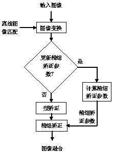
Active Publication Date: 2019-09-03
北京天睿空间科技股份有限公司
View PDF12 Cites 0 Cited by
  • Summary
  • Abstract
  • Description
  • Claims
  • Application Information

AI Technical Summary

Problems solved by technology

[0006] Existing chromatic aberration correction methods are roughly divided into two categories [1] : 1) Global correction, calculate a global correction coefficient for each image (one correction coefficient for each color channel), this method can make each image obtain an overall close tone, but the correction granularity is relatively coarse, and it is usually difficult to use only one global coefficient Describes the uneven color difference between images, so when the color difference is large, there are still obvious seams in the overlapping areas of the images
2) Local correction, the image is subdivided into different sub-blocks, and a correction coefficient is calculated for each sub-block. This method has a finer correction granularity, overcomes the shortcomings of global correction that is not enough to deal with local chromatic aberration, and can obtain a more accurate correction in the image overlapping area. Fine fusion effect, but does not correct the image sub-blocks in non-overlapping areas, thus making the transition from non-overlapping areas to overlapping areas appear unnatural
[0007] In addition, solving the fine-grained correction parameters requires a large amount of calculation and is difficult to complete in real time. Therefore, in video stitching, the parameters are usually only updated at a certain time interval (such as 0.5 to 2 minutes). , the illumination changes quickly, even if the parameter update frequency is once every half a minute, it still cannot adapt to the illumination change well

Method used


Image

  • Chromatic Aberration Correction Method Suitable for Video Stitching
  • Chromatic Aberration Correction Method Suitable for Video Stitching
  • Chromatic Aberration Correction Method Suitable for Video Stitching

Examples


Embodiment Construction

[0034] In order to facilitate the understanding of the present invention, the basic principle of chromatic aberration correction is briefly described below:

[0035] Generally, chromatic aberration correction can be expressed by the following formula:

[0036] I'(x,y)=gI(x,y) formula (1)

[0037] Among them, I represents the image before correction, g represents the correction coefficient, and I′ represents the image after correction. If I is a color image, each color channel is corrected with different g; if g is a constant, it corresponds to global correction. If As the pixel coordinates (x, y) change, it can be considered as local correction.

[0038] The calculation of the correction coefficient can be regarded as solving an optimization problem, so that the corresponding pixels of the corrected image in the overlapping area have the minimum square error, and its objective function can be expressed by the following formula [2] :

[0039]

[0040] Among them, n is the...


PUM


Abstract

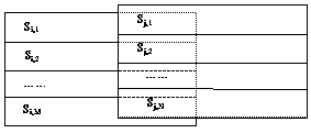
The invention relates to a color difference correction method suitable for video splicing, which includes: dividing an image into several sub-strips, using the sub-strips as correction units, calculating sub-strip correction coefficients adapted to each sub-strip respectively; dividing the image into several sub-strips. For sub-blocks, the sub-block is used as the correction unit to calculate the sub-block correction coefficient adapted to each sub-block. For any pixel in the image, the sub-strip correction coefficient of the sub-strip where it is located and the sub-block correction of the sub-block where it is located are calculated. The product of the coefficients is used as the fine correction coefficient of the pixel to finely correct the color difference. The pixel value after fine correction is the pixel value before fine correction multiplied by the corresponding fine correction coefficient. The present invention can better eliminate seams in overlapping areas of images while ensuring a natural transition effect between non-overlapping areas and overlapping areas, thereby improving the quality of spliced ​​images.

Description

technical field [0001] The invention relates to a color difference correction method suitable for video splicing. Background technique [0002] The technical basis of video stitching is image stitching, which combines several images with different perspectives but with certain overlapping areas into a panoramic image, which is widely used in security monitoring, remote sensing image processing, medical image analysis, virtual reality and other fields. [0003] Image mosaic usually includes two steps of image transformation and image fusion, in which image transformation is: through the extraction and matching of image feature points and the estimation of internal and external parameters of the camera, the geometric transformation model between each single image and panoramic image is established, and the image fusion is : The geometrically transformed images are fused to eliminate the stitching caused by imaging differences, such as different imaging sensors, different camer...

Claims


Application Information

Patent Timeline
Patent Type & Authority Patents(China)
IPC IPC(8): G06T5/00G06T3/40
CPCG06T3/4038G06T2207/10016G06T5/94
Inventor 吴刚林姝含郑文涛
Owner 北京天睿空间科技股份有限公司
Learn More