A TV socket

A ferrule and TV technology, which is applied in the direction of circuits, electrical components, conductive connections, etc., can solve problems such as easy loosening of the shielding layer, loose wiring, poor TV signals, etc., to reduce the influence of TV signals and increase the reliability of signal transmission , Enhance the effect of TV signal

Active Publication Date: 2020-08-14
温州佰正仪表科技有限公司
View PDF8 Cites 0 Cited by
  • Summary
  • Abstract
  • Description
  • Claims
  • Application Information

AI Technical Summary

Problems solved by technology

[0005] 1. The connection between the center pin and the copper core of the cable TV cable is not firm, and it is easy to loosen and fall off, resulting in poor TV signal and affecting the use of the TV;
[0006] 2. The structure of the TV insert is cumbersome, which reduces the disassembly efficiency between the TV insert and the cable TV line;
[0007] 3. The shielding layer of the cable TV cable is easy to loose, which leads to the deterioration of the TV signal and affects the use of the TV

Method used


Image

  • A TV socket
  • A TV socket
  • A TV socket

Examples


Embodiment 1

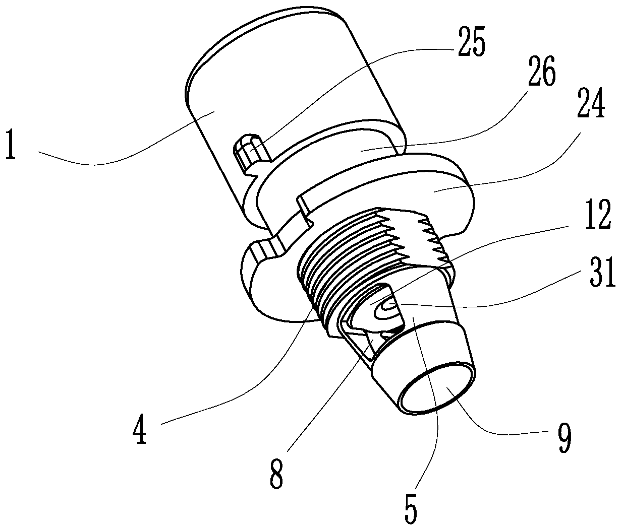
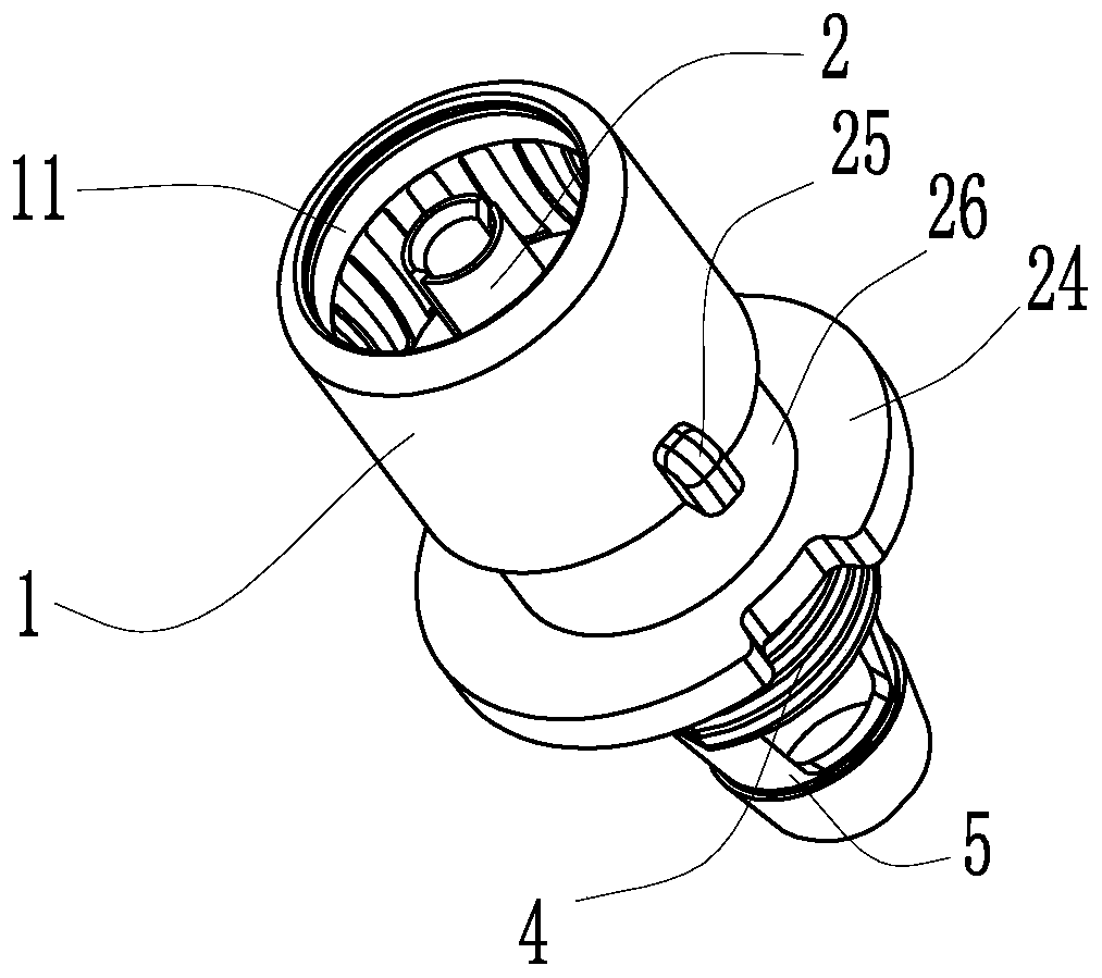
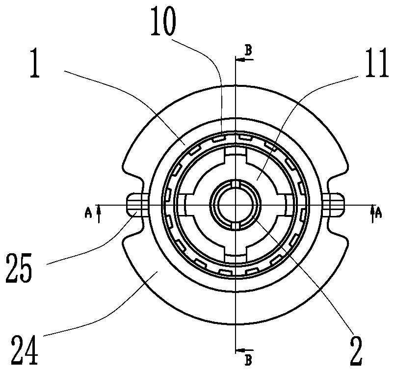
[0037] Embodiment one, such as Figures 1 to 10As shown, this embodiment discloses a TV ferrule, which includes a ferrule housing 1 and a ferrule center pin 2, and the lower part of the ferrule housing 1 is provided with an external thread part that is threadedly connected with a lock nut 3 4. The lower end of the external threaded part 4 is connected with a plug-in part 5 that is compatible with the lock nut 3. The plug-in part 5 is provided with a cable through hole 9 that is compatible with the cable TV cable 6. The plug-in part 5 It is arranged in a tapered structure and is also provided with a shielding through hole 8 that is compatible with the shielding layer 7 of the cable TV cable 6. The shielding layer 7 passes through the shielding through hole 8 and connects the ferrule housing 1 through the lock nut 3 The lower parts of the ferrule housing 1 are press-fitted and connected to each other, and the center of the upper part of the ferrule housing 1 is provided with an ...

Embodiment 2

[0042] Embodiment two, such as Figure 11 As shown, the difference between this embodiment and Embodiment 1 is that the angle between the two ends of the socket part 13 and the wiring part 14 is set to 120 degrees, and the angle is formed by the two ends of the installation through hole. The corners are the same; it is convenient for the installation and fixing of the TV insert as a whole.

[0043] Its installation process is as follows:

[0044] First place the protective cover 12 and the elastic ring 10 in the installation through hole of the ferrule housing 1, then place the fixing seat 11 on the center pin 2 of the ferrule, then cut the end of the cable TV cable 6 and place it The shielding layer 7 is left long, and then the cable TV cable 6 is inserted into the cable through hole 9, and then the shielding layer 7 of the cable TV cable 6 is passed through the shielding through hole 8, and the copper core 30 of the cable TV cable 6 is Penetrating through the guiding throu...


PUM


Abstract

The invention discloses a television ferrule. The key points of the technical scheme are as follows: the television ferrule includes a ferrule shell and a ferrule center needle; there is an external threaded part in threaded connection with a locking nut on the lower part of the ferrule shell; the lower end of the external threaded portion is connected with a plugging part matching the locking nut; the plugging part is provided with a cable through hole matching a cable television line; an installation through hole communicated with the cable through hole is arranged in the center of the upperpart of the ferrule shell, and the ferrule center needle is arranged in the installation through hole by penetrating; the ferrule center needle is sleeved with an elastic ring matching the inner wallof the ferrule shell, a fixed seat and a protective sleeve in turn from top to bottom; the ferrule center needle includes a plug bush part and a wiring part which are integrally formed; the plug bushpart and the wiring part are respectively provided with a plug bush opening and a wiring opening; and the end of the wiring opening forms a closing-in structure by stamping. The television ferrule ofthe invention has the effects of simple structure, reliable wiring and good television signal.

Description

technical field [0001] The invention relates to the technical field of TV signal transmission components, in particular to a TV socket. Background technique [0002] Cable TV cables are widely used as connection cables for transmitting TV radio frequency signals between TV networks and TV equipment (such as TV sets, set-top boxes, recorders / players, etc.), generally including copper cores, insulating layers outside the copper cores, The shielding layer over the insulating layer and the protective layer (skin) over the shielding layer. Usually, the connection between the cable TV lines is realized by inserting the TV socket plug which can meet the requirements of TV signal transmission into the TV socket of the receiver. With the popularization of TV and the rapid development of networked TV signal transmission technology, the application of TV sockets is getting wider and wider, and its performance requirements are getting higher and higher. These performances mainly includ...

Claims


Application Information

Patent Timeline
Patent Type & Authority Patents(China)
IPC IPC(8): H01R24/40H01R13/6592H01R9/05
CPCH01R9/0521H01R13/6592H01R24/40
Inventor 钱云成
Owner 温州佰正仪表科技有限公司
Why Eureka
Try Eureka