A phase-locked loop device applied to an FPGA chip and the FPGA chip

A phase-locked loop and chip technology, applied in the direction of automatic power control, electrical components, etc., can solve the problems of limited PLL configurability, inability to flexibly meet user application needs, poor flexibility, etc., to increase diversity and design flexibility sexual effect

Pending Publication Date: 2019-04-30
XIAN INTELLIGENCE SILICON TECH INC
View PDF10 Cites 2 Cited by
  • Summary
  • Abstract
  • Description
  • Claims
  • Application Information

AI Technical Summary

Problems solved by technology

[0004] However, the configurability of the existing PLL used in the FPGA chip is mostly limited, and most of them are statically configured, resulting in poor flexibility. Once the configuration of the PLL needs to be changed, the system needs to be stopped and reloaded. Therefore, it is impossible to flexibly meet the application needs of users

Method used


Image

  • A phase-locked loop device applied to an FPGA chip and the FPGA chip
  • A phase-locked loop device applied to an FPGA chip and the FPGA chip
  • A phase-locked loop device applied to an FPGA chip and the FPGA chip

Examples


Embodiment Construction

[0059] In order to make the above objects, features and advantages of the present invention more comprehensible, specific implementations of the present invention will be described in detail below in conjunction with the accompanying drawings.

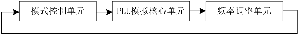
[0060] See figure 1 , figure 1 It is a schematic structural diagram of a phase-locked loop device provided by an embodiment of the present invention. An embodiment of the present invention provides a phase-locked loop device, the phase-locked loop device includes:

[0061] A mode control unit, configured to obtain a second reference clock according to the first reference clock, determine a first frequency division method according to a preset frequency division mode, and obtain a second feedback clock according to the first feedback clock and the first frequency division method;

[0062] A PLL analog core unit, connected to the mode control unit, for obtaining a second clock signal according to the second reference clock and the seco...


PUM


Abstract

The invention relates to a phase-locked loop device applied to an FPGA chip, and the device comprises a mode control unit which is used for obtaining a second reference clock according to a first reference clock, determining a first frequency division mode according to a preset frequency division mode, and obtaining a second feedback clock according to a first feedback clock and the first frequency division mode; a PLL analog core unit which is used for obtaining a second clock signal according to a second reference clock and a second feedback clock; And a frequency adjustment unit which is used for determining a second frequency division mode according to a preset frequency division mode and carrying out integer frequency division and/or non-integer frequency division on the second clocksignal according to the first frequency division mode and the second frequency division mode. According to the invention, the mode control unit, the PLL simulation core unit and the frequency adjustment unit are utilized, so that the phase-locked loop device can realize static configuration and dynamic configuration, and the application diversity and the design flexibility are improved.

Description

technical field [0001] The invention relates to the technical field of programmable logic units, in particular to a phase-locked loop device applied to an FPGA chip and the FPGA chip. Background technique [0002] Field-Programmable Gate Array (Field-Programmable Gate Array, FPGA chip) is a semi-customized circuit chip, which has abundant on-chip resources for development, flexible and convenient design methods, which not only solves the problem that customized circuits cannot be upgraded, but also overcomes the The shortcomings of the limited number of gate circuits of traditional programmable devices are eliminated. With the rise of artificial intelligence, higher requirements are put forward for the amount of data calculation and calculation speed, which also leads to the FPGA chip (Field-Programmable Gate Array, Field Programmable Gate Array) playing an increasingly important role in the field of accelerated computing. Many applications and services can significantly im...

Claims


Application Information

Patent Timeline
Patent Type & Authority Applications(China)
IPC IPC(8): H03L7/18H03L7/08
CPCH03L7/0805H03L7/18
Inventor 姬晶张祺孟智凯冯晓玲贾红陈维新韦嶔程显志
Owner XIAN INTELLIGENCE SILICON TECH INC
Why Eureka
Try Eureka