Supercharge Your Innovation With Domain-Expert AI Agents!

A hoisting slide rail type unloading rack

The technology of unwinding rack and sliding rail is applied in the field of feeding machinery, which can solve the problems of loosening of fastening bolts, broken material belt, excessive material belt surplus, etc., and achieves the effect of simple structure, good buffering effect, and avoiding material belt damage.

Active Publication Date: 2020-01-31
CHENGDU HOMIN TECH
View PDF6 Cites 0 Cited by
  • Summary
  • Abstract
  • Description
  • Claims
  • Application Information

AI Technical Summary

Problems solved by technology

[0002] The unwinding rack is a special unwinding device in the stamping production automation line. It is used to uncoil the material roll. At present, most of the unwinding racks commonly used in the market are vertical material racks. The control principle is that the material roll is conveyed to the subsequent leveling When the device is installed, it will droop a certain arc, and when the arc is too large, it will touch the induction rod, through the time relay and intermediate relay, and finally control the motor to stop; when the subsequent leveling machine continues to work, the arc of the material belt will become smaller, and the material will be It will disengage from the induction frame again, and the material frame motor will restart again to continue unwinding. This control method has two obvious defects: slow unwinding speed and low precision, which cannot be used in high-speed stamping occasions, and contact induction Easily scratches thin materials
In the process of continuous high-speed stamping, if the conveying speed of the material belt is slow, the material belt will suddenly generate tension, which sometimes causes the material belt to break; if the stamping speed is slow and the material belt conveying speed is too high, the material The belt will generate more surplus, causing the material belt to be held on the ground, which will cause the material belt to wear due to friction, and the fastening bolts of the traditional unwinding rack will usually loosen after a long period of use.
The above two situations often occur during the feeding process of the punching bed, but the existing punching bed does not have a buffering effect, usually after the tension or surplus of the material belt is sensed by the contact sensor, it passes through a series of controls. The controller controls the running speed of the unwinding rack

Method used


Image

  • A hoisting slide rail type unloading rack
  • A hoisting slide rail type unloading rack
  • A hoisting slide rail type unloading rack

Examples


Embodiment Construction

[0018] The technical solution of the present invention will be further described in detail below in conjunction with the accompanying drawings, but the protection scope of the present invention is not limited to the following description.

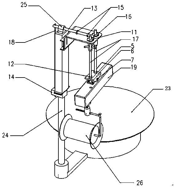
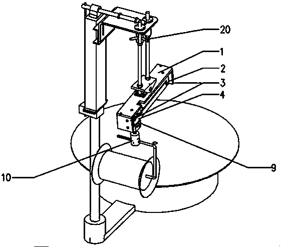
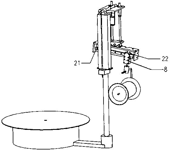
[0019] like Figure 1~3 As shown, a hoisting slide rail discharge rack is composed of a cover plate 1, a main board 2, a side plate 3, a trigger plate 4, a hinge support 5, a lifting lug 6, a shaft 7, a connecting plate 8, a connecting block 9, and a connecting plate. Column 10, shaft sleeve 11, adjusting nut 12, long axis 13, reinforcing block 14, clamp 15, L-shaped fixing plate 16, thick screw 17, thin screw 18, rectangular outer cover 19, adjusting handle 20, linear slide rail 21, Linear slide block 22, horizontal feed tray 23, support bar 24, fixed block 25 and support material wheel 26 form.

[0020] The connection method of a hoisting slide rail type discharge rack is as follows:

[0021] A lifting slide rail type discharge rack inc...


PUM


Abstract

The invention discloses a hoisting slide rail type unwinding rack, comprising a horizontal material disc (23) and a supporting rod (24). The horizontal material disc (23) and the supporting rod (24) are connected by a fixing support. The top of the supporting rod (24) is provided with a reinforcing block (14). The top of the reinforcing block (14) is provided with an upright column. The side wallof the upright column is provided with a U-shaped fixing rack. The side wall of the U-shaped rack is provided with an L-shaped fixing plate (16). The top of the L-shaped fixing plate (16) is providedwith a fixing assembly. The hoisting slide rail type unwinding rack is simple in structure; compared with a conventional unwinding rack, the hoisting slide rail type unwinding rack has a good buffering effect; and through a material supporting assembly and a fine adjustment assembly, the problem that a material belt is broken due to sudden tension or the material belt scrapes against the floor because of a surplus of the material belt can be effectively avoided.

Description

technical field [0001] The invention relates to the technical field of feeding machinery, in particular to a hoisting slide rail type discharging rack. Background technique [0002] The unwinding rack is a special unwinding device in the stamping production automation line. It is used to uncoil the material roll. At present, most of the unwinding racks commonly used in the market are vertical material racks. The control principle is that the material roll is conveyed to the subsequent leveling When the device is installed, it will droop a certain arc, and when the arc is too large, it will touch the induction rod, through the time relay and intermediate relay, and finally control the motor to stop; when the subsequent leveling machine continues to work, the arc of the material belt will become smaller, and the material will be It will disengage from the induction frame again, and the material frame motor will restart again to continue unwinding. This control method has two o...

Claims


Application Information

Patent Timeline
Patent Type & Authority Patents(China)
IPC IPC(8): B21C47/18B21C47/24B21C47/28
Inventor 杨翠刚赵琳刘文刚付涛杨国斌刘仁龙黄鹏
Owner CHENGDU HOMIN TECH
Features
  • R&D
  • Intellectual Property
  • Life Sciences
  • Materials
  • Tech Scout
  • Unparalleled Data Quality
  • Higher Quality Content
  • 60% Fewer Hallucinations
Learn More