Forging mold

A forging and model technology, applied in the field of forging models for manufacturing, can solve the problems that the material cannot be spread over the model, the hardness of the workpiece is insufficiently reduced, the fluidity of the model material is reduced, etc. The effect of defective products

Active Publication Date: 2019-05-03
JATCO LTD
View PDF18 Cites 3 Cited by
  • Summary
  • Abstract
  • Description
  • Claims
  • Application Information

AI Technical Summary

Problems solved by technology

[0007] However, in subthermal forging, the reduction in hardness of the workpiece due to heating is insufficient, and the fluidity of the material in the mold is reduced. Therefore, the material cannot spread throughout the mold, and in particular, the material cannot fill the above-mentioned parking gear part (in order to form a parking gear). The groove part of the model set for the gear), may become a defective product

Method used


Image

  • Forging mold
  • Forging mold
  • Forging mold

Examples


Embodiment Construction

[0038] Hereinafter, embodiments of the present invention will be described with reference to the drawings.

[0039] In addition, the embodiments shown below are merely examples, and various modifications and technical applications not explicitly described in the following embodiments are not excluded.

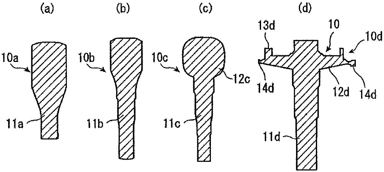
[0040] refer to figure 1 The process of machining a workpiece to manufacture a pulley shaft will be described.

[0041] First, as a pre-forging process, an unillustrated columnar workpiece made of high Si steel is heated to 1120° C. to 1160° C. (subthermal forging).

[0042] Afterwards, the forging process of the first process is carried out on the heated cylindrical workpiece to form a figure 1 (a) shows the first workpiece 10a with the minor axis 11a.

[0043] Next, the forging process of the second step is performed on the first workpiece 10a to form a figure 1 (b) shows the second workpiece 10b with the major axis 11b.

[0044] Next, the forging process of the third st...


PUM


Abstract

In a forging mold, in a step of molding a pulley shaft of a continuously variable transmission in which a shaft portion, a conical pulley portion, and a parking gear disposed on a rear surface side ofthe conical pulley portion are integrally manufactured by forging, a tooth crest of the parking gear is filled with a material. A mold (100) comprising upper and lower molds (104, 106) is provided with a release space (120) which extends outward in the radial direction of a pulley section and through which flashes flow out. The release space (120) has a first space formed radially outward of thetooth crest of the parking gear and a second space formed radially outward of the tooth bottom of the parking gear, and the flow resistance of the flash of the first space is set to be greater than the flow resistance of the flash of the second space.

Description

technical field [0001] The present invention relates to a forging mold for manufacturing a pulley shaft constituting a fixed pulley of a belt-type continuously variable transmission (hereinafter referred to as CVT), in particular to a forging model suitable for use on the back side of the pulley (the surface opposite to the pulley surface) and A forging model for manufacturing a pulley shaft whose pulley is integrally formed with a parking gear whose diameter is slightly smaller than the outer diameter of the pulley. Background technique [0002] A CVT mounted on a vehicle needs to be equipped with a parking mechanism, but it is known to integrally attach a parking gear constituting the parking mechanism to the rear side of a pulley surface of a fixed pulley (pulley shaft) (Patent Document 1). [0003] Patent Document 1: (Japanese) Unexamined Patent Publication No. 11-254084 [0004] In the case of manufacturing the above-mentioned pulley shaft by forging, steel with a sili...

Claims


Application Information

Patent Timeline
Patent Type & Authority Applications(China)
IPC IPC(8): B21J13/02B21K1/12
Inventor 大岛骏介权宁照
Owner JATCO LTD
Why Eureka
Try Eureka