Variable diameter pipe type positioning device

A technology for positioning devices and diameter tubes, which is applied in workpiece clamping devices, manufacturing tools, etc., can solve problems such as parts falling off, affecting processing accuracy, and easily causing safety accidents, so as to solve processing problems, ensure processing accuracy, and reduce processing costs. and the effect of operational difficulty

Pending Publication Date: 2019-05-03
吉林瑞丰重工有限公司
View PDF7 Cites 0 Cited by
  • Summary
  • Abstract
  • Description
  • Claims
  • Application Information

AI Technical Summary

Problems solved by technology

China Invention Patent Application No. 201610660152.3, which discloses the name "A Round Tube Positioning Device", which uses a bottom positioning die, an upper compression die, a left V-shaped block, a right V-shaped block, a left-handed thread nut slider, and a right-handed thread The structure of the female slider and the two-way lead screw is positioned and clamped from four directions of the round tube, but it is not suitable for positioning and clamping of thin-walled tube parts. When clamping thin-walled tube parts, due to the thin tube wall, the application If the clamping force is too large, the internal stress of the tube wall will be damaged, and the thin-walled tube will be seriously deformed, which will affect the processing accuracy; if the clamping force is too small, the thin-walled tube parts will not be able to be clamped, and the positioning will be inaccurate during processing, and the parts will If it falls off, it is easy to cause a safety accident
In addition, during the processing of pipe parts, the pipe parts need to be rotated to complete the surface processing of pipe parts; if the pipe parts do not rotate, CNC machine tools are required to complete the surface processing of pipe parts, but the processing cost of CNC machine tools is high and the operation High difficulty

Method used


Image

  • Variable diameter pipe type positioning device
  • Variable diameter pipe type positioning device
  • Variable diameter pipe type positioning device

Examples


Embodiment Construction

[0019] The following is attached Figure 1-5 The present invention will be further described in detail with specific examples, and the specific examples described here are only used to explain the present invention, and are not intended to limit the present invention.

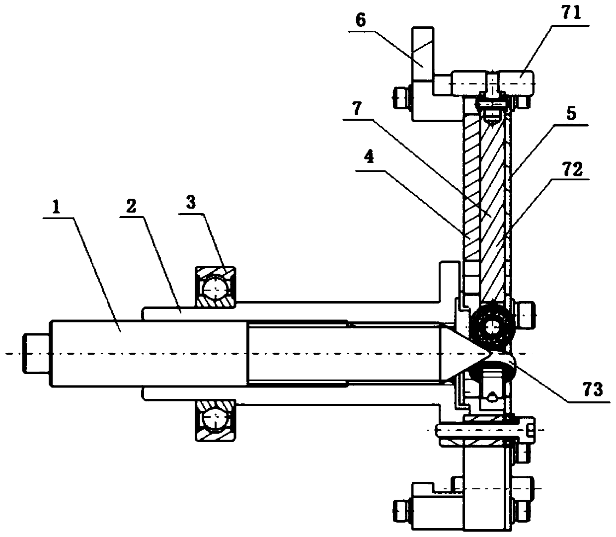
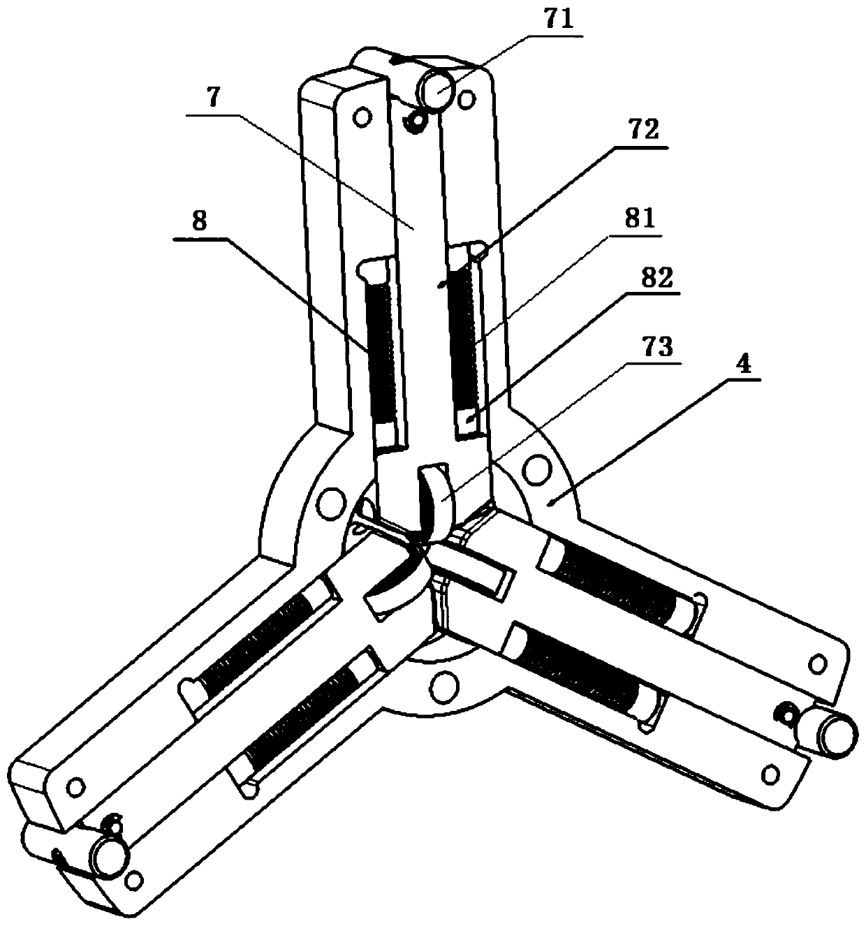
[0020] Refer to attached Figure 4 As shown, the telescopic positioning rod 7 includes a positioning shaft 71, a connecting rod 72, and a passive guide body 73. The positioning shaft 71 is fixedly connected to one end of the connecting rod 72, and the center line of the positioning shaft 71 is connected to the power push rod. 1 parallel to the central line, the passive guide body 73 is fixedly connected to the other end of the connecting rod 72, and the passive guide body 73 is arranged at the center hole of the base body 4.

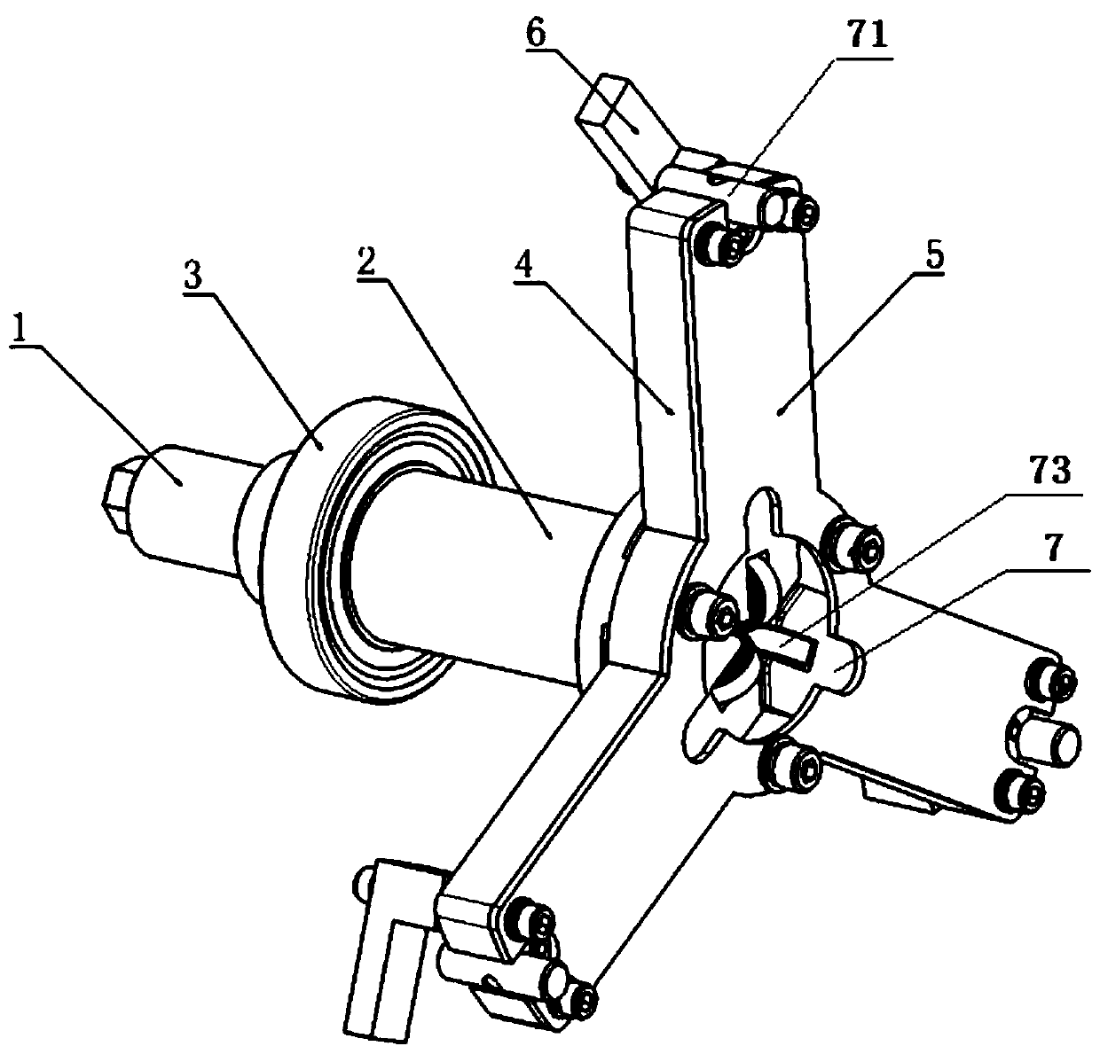
[0021] Refer to attached Figure 1-3 As shown, a variable-diameter pipe positioning device includes: a power push rod 1, a connecting sleeve 2, a base body 4, a gland 5, a telescopic po...


PUM


Abstract

The invention provides a variable diameter pipe type positioning device. The variable diameter pipe type positioning device comprises a power push rod, a connecting sleeve, a base body, a pressing cover, a telescopic positioning rod and an elastic supporting body, the spiral power push rod is adjusted step by step, the power push rod pushes the telescopic positioning rod to advance, clamping forceis accurately applied, as the telescopic positioning rod can adjust a stroke and can position and clamp parts with different pipe diameters, pipe internal stress is not broken, the machining precision is ensured, and the machining problem of thin-wall pipe type parts is effectively solved; and meanwhile, a dividing device can be matched to realize positioning and clamping of the pipe type parts,meanwhile, rotation of the pipe type parts to be machined can be realized, outer surface machining of the pipe type parts is completed, the machining precision of the pipe type parts is ensured, and the machining cost and the operating difficulty are reduced.

Description

technical field [0001] The invention relates to a positioning device, in particular to a variable-diameter pipe positioning device. Background technique [0002] During machining, the position of the workpiece needs to be determined according to specific requirements in order to ensure its machining accuracy. During the processing of various round tube materials, it needs to be positioned and clamped. China Invention Patent Application No. 201610660152.3, which discloses the name "A Round Tube Positioning Device", which uses a bottom positioning die, an upper compression die, a left V-shaped block, a right V-shaped block, a left-handed thread nut slider, and a right-handed thread The structure of the female slider and the two-way lead screw is positioned and clamped from four directions of the round tube, but it is not suitable for positioning and clamping of thin-walled tube parts. When clamping thin-walled tube parts, due to the thin tube wall, the application If the cla...

Claims


Application Information

Patent Timeline
Patent Type & Authority Applications(China)
IPC IPC(8): B25B11/00
Inventor 郭东吴冰谢景全李德龙姜丽影
Owner 吉林瑞丰重工有限公司
Why Eureka
Try Eureka