
Modularized space multi-stable configuration-varying robot

A multi-stable and modular technology, applied in the field of robotics, can solve the problems of rapid decay of mechanical properties of soft materials, sensitive to ambient temperature and humidity, and difficulty in achieving large variable stiffness ratios, so as to reduce the difficulty of control and reduce the difficulty of control. Usability-enhancing effects

Active Publication Date: 2019-05-03
XI AN JIAOTONG UNIV
View PDF6 Cites 0 Cited by
  • Summary
  • Abstract
  • Description
  • Claims
  • Application Information

AI Technical Summary

Problems solved by technology

The flexible / soft structure greatly enhances the robot's ability to adapt to the environment, but it is difficult to achieve a large variable stiffness ratio (that is, the ratio of maximum stiffness to minimum stiffness). For example, the variable stiffness ratio achieved by the Ohio State Soviet Navy in 2018 was only 20 ; In addition, the mechanical properties of soft materials decay quickly and are sensitive to environmental temperature and humidity, which is the bottleneck for the current engineering application of soft robots

Method used


Image

  • Modularized space multi-stable configuration-varying robot
  • Modularized space multi-stable configuration-varying robot
  • Modularized space multi-stable configuration-varying robot

Examples


Embodiment 1

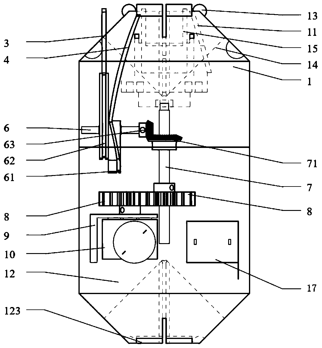
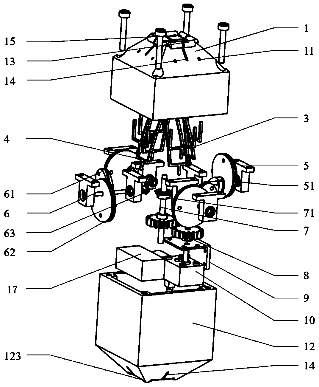
[0043] like figure 1 , figure 2 As shown, the upper half shell 1 of the main body and the lower half shell 12 of the main body are both a decahedron shell-shaped structure composed of a square prism and a square truss, and are connected by four screws 2 to form a 14-sided unit shape structure .

[0044] The inside of described main body lower half shell 12 is equipped with power supply 17 and motor support 9, and motor support 9 installs reduction motor 10; The reduction motor 10, the spur gear transmission group, the bevel gear transmission group, and four sets of camshafts 6 form a single-input-four-output bevel gear transmission.

[0045] The two spur gears 8 form a spur gear train.

[0046] The second bevel gear 71 and the four first bevel gears 63 form a bevel gear transmission set.

[0047] The inside of the upper half shell 1 of the main body is installed with 4 groups of centering roller push rod disc cam machines composed of bearing housing 5, camshaft 6, linear ...

Embodiment 2

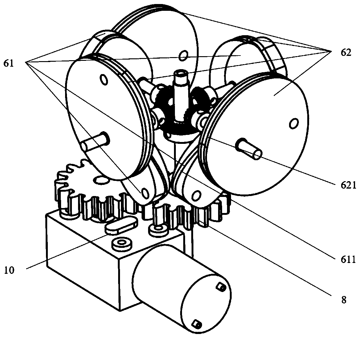
[0050] like image 3 As shown, the single-input and four-output bevel gear transmission includes at least four camshafts 6 , transmission shafts 7 , spur gears 8 , and reduction motors 10 . The camshaft 6 includes a first cam 61, a first cam guide groove 611, a second cam 62, a second cam guide groove 621, and a first bevel gear 63, and the transmission shaft 7 includes a second bevel gear 71 and a spur gear 8;

[0051] The geared motor 10 is a 24v DC geared motor, model JGY370, with a rotating speed of 10 rpm. The motor adopts a worm gear to reduce the torque, and has a large torque and strong self-locking ability.

[0052] Described two spur gears 8 form spur gear transmission group, and two spur gears are identical, all select 2 molds for use, 16 teeth.

[0053] The second bevel gear 71 and four first bevel gears 63 form a bevel gear transmission group, the second bevel gear 71 is selected with 0.5 mold 40 teeth, and the first bevel gear 63 is selected with 0.5 mold 20 tee...

Embodiment 3

[0056] like Figure 4 As shown, the center roller push rod disc cam mechanism at least includes the upper half shell 1 of the main body, the linear push rod 3, the arc push rod 4, the bearing seat 5, and the camshaft 6. The upper shell 1 of the main body contains four linear push rod guide grooves 11 and four arc push rod guide grooves 15, the linear push rod 3 includes the upper end of the linear push rod and the lower end of the linear push rod, and the arc push rod 4 includes arc The upper end of the push rod and the lower end of the arc push rod, the bearing housing 5 includes a bearing 51 , and the camshaft 6 includes a first cam 61 , a first cam guide groove 611 , a second cam 62 , and a second cam guide groove 621 .

[0057] In the camshaft 6, the first cam 61 and the second cam 62 are distributed with an angle difference of 135 degrees. The first cam guide groove 611 of the first cam 61 is rollingly connected with the arc push rod lower end of the arc push rod 4, and ...


PUM


Abstract

The invention discloses a modularized space multi-stable configuration-varying robot. The modularized space multi-stable configuration-varying robot comprises a plurality of module units and a rope, wherein each module unit is internally provided with a through hole, the rope sequentially penetrates through the module units to connect the plurality of module units together to form the modularizedspace multi-stable configuration-varying robot, the module units comprise shells, driving devices, cam devices, push rod devices, push rod grooves and rope guide grooves, the driving devices are arranged at the inner bottoms of the shells, the cam devices are arranged at the upper ends of the driving devices, the driving devices are used for driving the cam devices to rotate, the push rod devicesare arranged at the upper ends of the cam devices, the cam devices drive the push rod devices to move up and down, the push rod grooves and the rope guide grooves are formed inside the shells, the push rod devices are inserted into the push rod grooves, and the rope is arranged in the rope guide grooves. In the aspect of the configuration varying capacity of the same rank, compared with other configuration-varying robots, the modularized space multi-stable configuration-varying robot has the characteristics that structure is obviously simple, and the cost is also reduced accordingly.

Description

technical field [0001] The invention belongs to the field of robots, in particular to a modular space multi-stable configuration-changing robot. Background technique [0002] Robots that can adapt to changing environments, complete multiple tasks, and serve multiple types of objects have great application value in fields such as space exploration, future battlefield support, underwater operations, and medical rehabilitation. The ability to change configurations and the ability to change the robot's stiffness quickly and in a wide range under different configurations is the key to realizing the characteristics of the above-mentioned robots. [0003] The research on the configuration-changing robot can be roughly divided into the following three branches: 1. Starting from the kinematics of the mechanism, the degree of freedom and motion mode of the mechanism can be changed by using the structural topology change of the mechanism. Representative achievements include: the metam...

Claims


Application Information

Patent Timeline
Patent Type & Authority Applications(China)
IPC IPC(8): B25J9/06B25J9/08B25J9/16
Inventor 陈贵敏孙诚程李博
Owner XI AN JIAOTONG UNIV
Learn More