
Capillary hung ceiling paving method and capillary network temperature adjusting system

A laying method and capillary technology, applied in space heating and ventilation details, ceilings, heating methods, etc., can solve problems such as loss, capillary radiation heat loss, and affecting indoor net height

Inactive Publication Date: 2019-05-03
SHANGHAI LANDLEAF BUILDING TECH CO LTD
View PDF7 Cites 1 Cited by
  • Summary
  • Abstract
  • Description
  • Claims
  • Application Information

AI Technical Summary

Problems solved by technology

[0004] However, at present, the capillary tubes used in the capillary network air-conditioning system are installed in the form of a suspended ceiling when they are laid on the roof. The keel structure used in the suspended ceiling includes a hanging piece, a main keel, and an auxiliary keel. The hanging piece is fixedly connected to the floor. The main keel is hoisted on the lower side of the hanger, and the auxiliary keel is set on the lower side of the main keel. The installation height of the entire keel structure will be greater than 100mm, which will greatly affect the indoor net height.
Moreover, there is a large cavity between the capillary and the floor, and the heat or cooling released by the capillary will be lost in the cavity, which affects the heat exchange efficiency of the capillary and causes the problem of anisotropic loss of capillary radiated heat.

Method used


Image

  • Capillary hung ceiling paving method and capillary network temperature adjusting system
  • Capillary hung ceiling paving method and capillary network temperature adjusting system
  • Capillary hung ceiling paving method and capillary network temperature adjusting system

Examples


Embodiment Construction

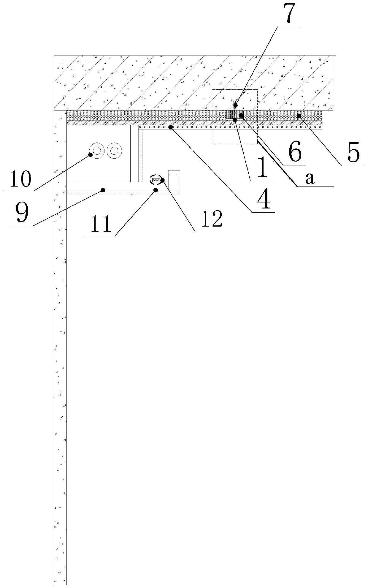
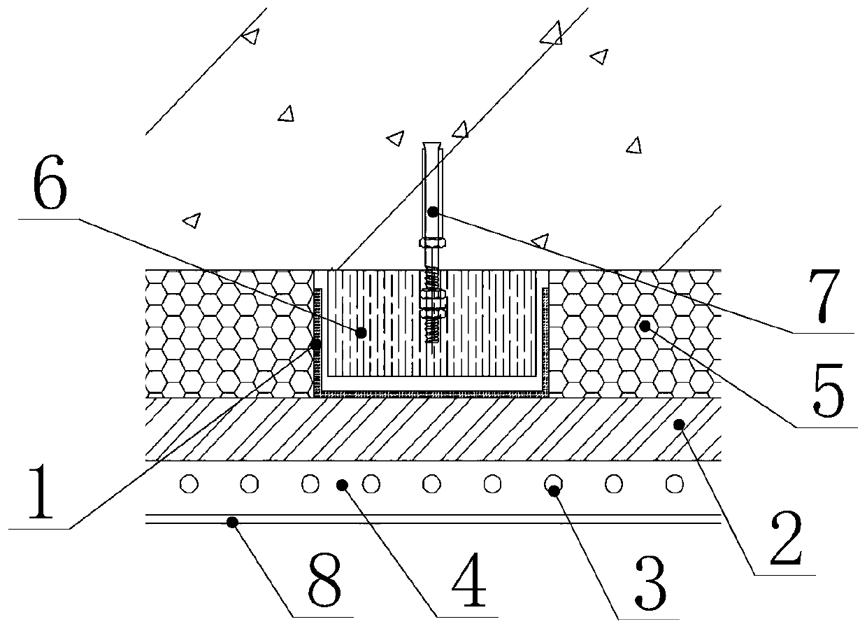
[0029] In order to more clearly illustrate the embodiments of the present invention or the technical solutions in the prior art, the specific implementation manners of the present invention will be described below with reference to the accompanying drawings. Obviously, the accompanying drawings in the following description are only some embodiments of the present invention, and those skilled in the art can obtain other accompanying drawings based on these drawings and obtain other implementations.

[0030] In order to make the drawing concise, the parts related to the present invention are only schematically shown in each drawing, and they do not represent the actual structure of the product.

[0031] The traditional capillary network air-conditioning system adopts a very complicated keel structure, which not only has many components, but also seriously affects the indoor net height and causes energy loss. Thickness dimension is larger.

[0032] Please refer to figure 1 and...


PUM

PropertyMeasurementUnit
Thicknessaaaaaaaaaa
Thicknessaaaaaaaaaa
Thicknessaaaaaaaaaa

Abstract

The invention discloses a capillary hung ceiling paving method and a capillary network temperature adjusting system. The capillary network temperature adjusting system comprises capillaries, main pipes connected with the capillaries and auxiliary keels; the thickness of the auxiliary keels is not greater than 30mm, a water-proof board is arranged through the auxiliary keels, the thickness of the water-proof board is in the range of 11-13mm, and the capillaries are paved on the lower side of the water-proof board; and a structural layer for coating the capillaries and with the thickness not less than the capillaries is formed on the lower side surface of the water-proof board through mortar spraying, a heat dissipation fiber screen for heat dissipation is formed by the structural layer andthe capillaries, and the thickness of the structural layer is in the range of 12-15mm. The capillary network temperature adjusting system is only provided with the auxiliary keels, the overall thickness of the auxiliary keels is not greater than 30mm, compared with a traditional keel structure with the thickness greater than 100mm, the structural design can decrease the overall thickness of the capillary network temperature adjusting system to a great extent, and the problem of capillary energy loss existing in a capillary network air conditioning system is solved.

Description

technical field [0001] The invention relates to the technical field of room temperature adjustment systems, and more specifically, to a method for laying a capillary ceiling and a capillary network temperature adjustment system. Background technique [0002] The room temperature adjustment is usually realized by the air conditioning system, that is, the air conditioning system exchanges heat with the external environment to provide heat or cold for the room. The air-conditioning system adopts a "point-to-surface" temperature adjustment method, which will cause the temperature around the air conditioner to be close to the target temperature, while the temperature far away from the air conditioner will be quite different from the target temperature. Moreover, the air-conditioning system uses fans to exchange heat indoors by blowing air, which will cause problems such as high operating noise and low physical comfort. [0003] In order to solve the above problems, a new type of...

Claims


Application Information

Patent Timeline
IPC IPC(8): E04B9/00E04B9/06F24F13/00F24F13/30
Inventor 黄家敏
Owner SHANGHAI LANDLEAF BUILDING TECH CO LTD
Learn More