Vacuum rotating assisting device with fan-shaped iron handles

A fan-shaped, iron handle technology, applied in the direction of transmission, belt/chain/gear, mechanical equipment, etc., can solve the problem of large energy consumption of the prime mover, the kinetic energy of the prime mover cannot be increased, and the kinetic energy of the prime mover cannot be increased. problem, to achieve the effect of improving kinetic energy, saving energy consumption and increasing mechanical energy output

Pending Publication Date: 2020-05-29
杨晓东
View PDF0 Cites 0 Cited by
  • Summary
  • Abstract
  • Description
  • Claims
  • Application Information

AI Technical Summary

Problems solved by technology

[0004] The technical problem to be solved by the present invention is that in the existing wheel shaft transmission system, the energy consumption of the prime mover is large, and the kinetic energy of the prime mover cannot increase with the increase of the speed. The purpose is to provide a vacuum fan-shaped iron handle to assist rotation The device solves the problem that the kinetic energy of the prime mover cannot increase with the increase of the speed in the existing wheel shaft transmission system.

Method used


Image

  • Vacuum rotating assisting device with fan-shaped iron handles
  • Vacuum rotating assisting device with fan-shaped iron handles
  • Vacuum rotating assisting device with fan-shaped iron handles

Examples


Embodiment 1

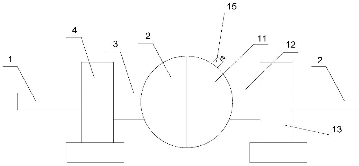
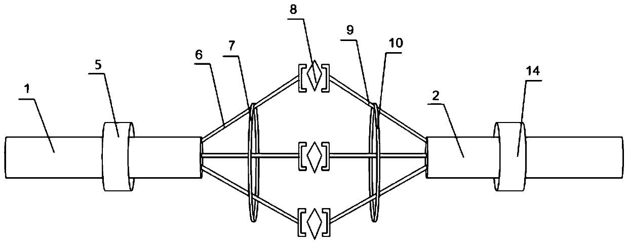
[0031] Such as Figure 1-5 As shown, a vacuum fan-shaped iron handle rotation assisting device of the present invention includes a power input shaft 1 and a power output shaft 2, the outer end of the power input shaft 1 is connected with the prime mover output shaft, and the inner end of the power input shaft 1 is sleeved with The first hemispherical cover 2, the convex surface of the first hemispherical cover 2 is equipped with the first shaft sleeve 3 for power input shaft 1 to insert, one end of the first shaft sleeve 3 communicates with the first hemispherical cover 2, the first shaft sleeve 3 The other end communicates with the first bearing seat 4, the power input shaft 1 is connected with the first bearing seat 4 through the first bearing 5 with a seal, and the power input shaft 1 is installed at least Three first spokes 6 that are singular in number, the inner side of the power input shaft 1 is equipped with a first annular ring 7 coaxial with it, and all the first spo...

Embodiment 2

[0036] Based on Example 1, the surface layer and the inner layer of the first hemispherical cover 2 and the second hemispherical cover 11 are all coated with a heat insulating layer. The heat insulation layer is used to prevent the system from being heated and causing air resistance to affect the normal operation of the system. The heat insulation layer can use glass fiber, asbestos, rock wool, silicate, airgel felt, vacuum board, etc.


PUM


Abstract

The invention discloses a vacuum rotating assisting device with fan-shaped iron handles. The vacuum rotating assisting device comprises a power input shaft and a power output shaft. The power input shaft is sleeved with a first hemispherical cover, and a first shaft sleeve is mounted on the first hemispherical cover. The first shaft sleeve communicates with a first bearing pedestal, and at least three singular first spokes are mounted at the inner end, on the inner side of the first hemispherical cover, of the power input shaft. A first annular ring is mounted on the inner side of the power input shaft, and the other end of each first spoke is connected with an energy gathering fan-shaped iron handle. The other side of each energy gathering fan-shaped iron handle is connected with a secondspoke. The second spokes are connected to the power output shaft. A second annular ring is mounted on the inner side of the power output shaft, and the inner end of the power output shaft is sleevedwith a second hemispherical cover. A second shaft sleeve is mounted on the convex face of the second hemispherical cover, and the second shaft sleeve communicates with a second bearing pedestal. According to the vacuum rotating assisting device with the fan-shaped iron handles, the problem that the kinetic energy of a prime motor cannot be remarkably increased along with rise of the speed is solved.

Description

technical field [0001] The invention relates to a rotation-assisting device, in particular to a vacuum fan-shaped iron handle rotation-assisting device. Background technique [0002] How to reduce energy consumption and use cost of mechanical equipment in production, life and service is the fundamental desire of most manufacturers and users. Enterprises hope to improve the effective use of energy through various technological improvements in the process of transformation and upgrading and intelligent manufacturing. Rate. In recent years, through the unremitting efforts and continuous innovation of technicians and craftsmen, the machinery manufacturing industry has made gratifying achievements in increasing speed and efficiency. [0003] Even so, there is still a lot of room for improvement in some power systems, especially the working efficiency of the prime mover is not ideal, and some power and transmission systems have problems of insufficient power utilization and many ...

Claims


Application Information

Patent Timeline
Patent Type & Authority Applications(China)
IPC IPC(8): F16H35/18
CPCF16H35/18
Inventor 杨晓东
Owner 杨晓东
Why Eureka
Try Eureka