High-power wireless charging test mechanism

A technology for wireless charging and testing institutions, which is used in electric power measurement through current/voltage, current collectors, electric vehicles, etc., can solve the problems of heavy weight, complicated and troublesome operation, and difficult to guarantee adjustment accuracy, and achieves a high degree of automation and improved The effect of testing efficiency

Inactive Publication Date: 2019-05-03
SOUTHWEAT UNIV OF SCI & TECH
View PDF12 Cites 7 Cited by
  • Summary
  • Abstract
  • Description
  • Claims
  • Application Information

AI Technical Summary

Problems solved by technology

The traditional wireless charging test, the adjustment of the relative offset between the transmitting coil system 600 and the receiving coil system 700, as well as the adjustment of the distance between the two coils, the overall displacement of the two coils and other relative position changes are all done manually. , since the transmitting coil system 600 and receiving coil system 700 occupy a large area and are heavy, the operation is complicated and cumbersome, and the adjustment accuracy is difficult to guarantee, and the test is troublesome
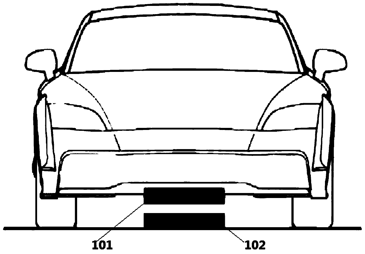
[0004] At present, the existing high-power wireless charging testing organization, for example, is a Chinese invention patent application document with a publication number of CN106597084A and a publication date of April 26, 2017, which relates to a test system for a wireless charging system for electric vehicles, including: Measuring system, receiving system, transmitting system and mechanical platform. The mechanical platform is equipped with a matching transmitting coil system 600 and receiving coil system 700. The structural connection between the mechanical platforms cannot completely simulate the receiving coil and transmitting electric coil when the vehicle is charging. The position changes between them mainly include the actual charging situation of the vertical distance change, the deflection of the body axis, and the tilt of the body.

Method used


Image

  • High-power wireless charging test mechanism
  • High-power wireless charging test mechanism
  • High-power wireless charging test mechanism

Examples


Embodiment 2

[0094] The difference between this embodiment and the above-mentioned embodiment is that the X-axis sliding assembly 200 and the Y-axis sliding assembly 300 can be arranged on the same plane, and the X-axis sliding assembly 200 and the Y-axis sliding assembly 300 are used as the high-power wireless charging test mechanism. At the same time as the load-bearing parts, it can realize the degrees of freedom in the X and Y axes. When the X-axis sliding assembly 200 and the Y-axis sliding assembly 300 can be arranged on the same plane, the X-axis sliding assembly 200 and the Y-axis sliding assembly 300 can be arranged on the same support portion 205 .

Embodiment 3

[0096] The difference between this embodiment and the above-mentioned embodiments is that the upper plate 402 and the lower plate 403 of the independent rotating platform 400 can also be set to the same size, and the lower plate 403 and the upper plate 402 can cooperate with the rotary support turntable bearing 401 to realize a high-power wireless charging test mechanism Rotation in the Z-axis direction.

Embodiment 4

[0098] The difference between this embodiment and the above-mentioned embodiment is that the step screw linear motor assemblies 502 of the gimbal 500 are set in 6 groups, and each group shares one upper bearing seat 506, three upper bearing seats 506, and the formed triangle can make The position is stable, and then the small-angle pitch of the transmitting coil is realized, and the tilt state of the simulated real wireless charging vehicle is realized.


PUM


Abstract

The invention provides a high-power wireless charging test mechanism comprising a transmitting coil system, a receiving coil system disposed on an automobile, an independent rotating platform for driving the transmitting coil system to rotate, and a universal table for driving the transmitting coil system to turn over. Therefore, various states of two coils during the actual wireless charging process can be simulated; the automation degree of the testing is increased; and the testing efficiency is improved. And a solution is provided for high-power wireless charging of the electric vehicle.

Description

technical field [0001] The invention relates to the field of wireless charging, in particular to a high-power wireless charging testing mechanism. Background technique [0002] With the popularization of electric vehicles, there are more and more vehicle charging facilities, and vehicle wireless charging has attracted more and more attention from all parties due to its convenience. Due to factors such as vehicle parking, the physical position of the transmitting coil on the ground and the receiving coil on the car is difficult to be in the optimal alignment state of the design, which will adversely affect the performance and efficiency of the wireless charging system. How to evaluate this situation requires specific testing of the wireless charging system. The position changes between the receiving coil and the transmitting coil when the vehicle is charging mainly include vertical distance changes, horizontal front and rear or left and right offsets, body axis deflection, a...

Claims


Application Information

Patent Timeline
Patent Type & Authority Applications(China)
IPC IPC(8): G01R21/06H02J7/02H02J50/10
Inventor 朱玉玉范峻金洪锡
Owner SOUTHWEAT UNIV OF SCI & TECH
Why Eureka
Try Eureka