Cutting device for new energy automobile product wire harnesses

A new energy vehicle and cutting device technology, applied in the manufacture of wire harnesses, transportation and packaging, pile separation, etc., can solve the problems of increased labor costs, production costs, unfavorable long-term development of enterprises, and unsuitable for mass production, etc., to reduce labor costs The effect of cost expenditure, novel design, accuracy and efficiency improvement

Active Publication Date: 2020-07-31
TONGCHENG SINBON ELECTRONICS
View PDF5 Cites 6 Cited by
  • Summary
  • Abstract
  • Description
  • Claims
  • Application Information

AI Technical Summary

Problems solved by technology

[0002] With the development of industry, wire harness is a necessary part of mechanical equipment, and it should have a wide range. However, the location and use of wire harness in mechanical equipment are different, so the required length also needs to be customized. The existing wire harness cutting Generally, manual cutting is used, but the efficiency of manual cutting is low, the accuracy is not high, it is not suitable for mass production, and the expenditure of labor costs will increase the production cost, which is not conducive to the long-term development of the enterprise

Method used


Image

  • Cutting device for new energy automobile product wire harnesses
  • Cutting device for new energy automobile product wire harnesses
  • Cutting device for new energy automobile product wire harnesses

Examples


Embodiment Construction

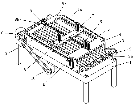
[0030] In order to facilitate the understanding of the present invention, the present invention will be described more fully below with reference to the relevant drawings, in which several embodiments of the present invention are shown, but the present invention can be realized in different forms, and is not limited to the text described On the contrary, these embodiments are provided to make the disclosure of the present invention more thorough and comprehensive.

[0031] It should be noted that when an element is said to be "fixed on" another element, it can be directly on the other element or there can be an intervening element, and when an element is said to be "connected" to another element, it can be Directly connected to another element or possibly intervening elements at the same time, the terms "vertical," "horizontal," "left," "right," and similar expressions are used herein for purposes of illustration only.

[0032] Unless otherwise defined, all technical and scien...


PUM


Abstract

The invention discloses a cutting device for new energy automobile product wire harnesses. The device comprises a cutting workbench, two guiding roller assemblies are symmetrically arranged at the front end and the rear end of the cutting workbench, a wire cutting base is arranged between the two guiding roller assemblies, a U-shaped cover cap is arranged at the upper end of the wire cutting base,the U-shaped cover cap is arranged in an inverted covering mode, the bottoms of the left side and the right side of the U-shaped cover cap are fixed to the edges of the left side and the right side of the cutting workbench, a working opening is formed in the top of the U-shaped cover cap, a blocking mechanism and a conveying mechanism are sequentially arranged on a top plate at one end of the U-shaped cover cap, the conveying mechanism is located between the blocking mechanism and the working opening, and a cutting mechanism is slidably arranged at the upper end of the working opening. According to the device, automatic batch cutting work of the wire harnesses is well achieved, the accuracy and efficiency are well improved, and meanwhile, the labor cost expenditure is reduced, and more profit margins are brought to enterprises.

Description

technical field [0001] The invention mainly relates to the technical field of wire harness processing equipment, in particular to a cutting device for wire harnesses of new energy automobile products. Background technique [0002] With the development of industry, wire harness is a necessary part of mechanical equipment, and it should have a wide range. However, the location and use of wire harness in mechanical equipment are different, so the required length also needs to be customized. The existing wire harness cutting Generally, manual cutting is used, but the efficiency of manual cutting is low, the accuracy is not high, it is not suitable for mass production, and the expenditure of labor costs will increase the production cost, which is not conducive to the long-term development of the enterprise. Contents of the invention [0003] The present invention mainly provides a cutting device for wire harnesses of new energy automobile products to solve the technical problem...

Claims


Application Information

Patent Timeline
Patent Type & Authority Applications(China)
IPC IPC(8): B21F11/00B21F23/00B21C51/00H01B13/012B65H5/06B65H29/20
CPCB21F11/00B21F23/00B21C51/00H01B13/01209H01B13/01236B65H5/06B65H29/20
Inventor 赵占兵
Owner TONGCHENG SINBON ELECTRONICS
Why Eureka
Try Eureka