Automatic phase adjustment unit and an adjustment method

A phase adjustment and automatic technology, applied in optical components, optics, instruments, etc., can solve the problems of complex phase adjustment system and difficulty in phase adjustment, and achieve the effect of short phase adjustment time and good self-applicability

Inactive Publication Date: 2019-05-03
BEIJING RES INST OF SPATIAL MECHANICAL & ELECTRICAL TECH
View PDF12 Cites 3 Cited by
  • Summary
  • Abstract
  • Description
  • Claims
  • Application Information

AI Technical Summary

Problems solved by technology

However, this kind of common phase adjustment technology needs to equip each sub-mirror with a set of micro-displacement mechanical adjustment mechanism and auxiliary adjustment mechanism. The phase adjustment system is complicated and the phase adjustment is difficult.

Method used


Image

  • Automatic phase adjustment unit and an adjustment method
  • Automatic phase adjustment unit and an adjustment method
  • Automatic phase adjustment unit and an adjustment method

Examples


Embodiment Construction

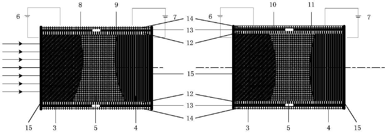
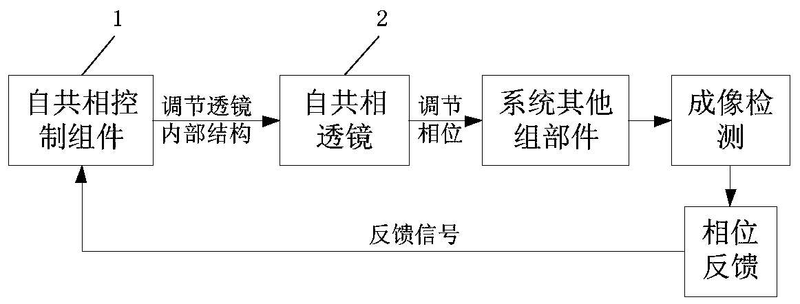
[0028] The composition diagram of an automatic phase adjustment unit of the present invention is as follows figure 1 As shown, the entire automatic phase adjustment unit is composed of a self-common phase control component 1 and a self-common phase lens 2, wherein the self-common phase lens 2 is filled with conductive liquid and non-conductive liquid, and the self-common phase lens 2 is controlled by the self-common phase control component 1 is controlled to make the liquid interface inside the eutectic lens 2 deform, thereby realizing phase adjustment.

[0029] Self-cophasic lens 2 includes first conductive liquid 3, second conductive liquid 4, non-conductive liquid 5, first conductive liquid voltage control system 6, second conductive liquid voltage control system 7, first conductive solution first interface 8, The first interface 9 of the second conductive solution, the second interface 10 of the first conductive solution, the second interface 11 of the second conductive so...


PUM


Abstract

The invention relates to an automatic phase adjustment unit and an adjustment method. The adjustment unit comprises a self-in-phase control assembly and a self-in-phase lens. The self-in-phase lens isfilled with conductive liquid and non-conductive liquid and is controlled by the self-in-phase control assembly and thus the internal liquid interface of the self-in-phase lens deforms, thereby realizing phase adjustment. According to the invention, the liquid lens based on the dielectric wetting effect is used for realizing effective modulation of the light phase effectively. The adjustment unithas characteristics of mechanical moving part prevention, high self-adaptability, short response time and good integration performance. A novel way of in-phase adjustment of spliced sub mirrors is provided. The automatic phase adjustment unit and an adjustment method are applied to the distributed synthetic aperture optical interference imaging system, thereby reducing the design difficulty of the system and greatly improving the imaging quality.

Description

technical field [0001] The invention relates to an automatic phase adjustment unit and an adjustment method, which is a novel method for effectively adjusting the light passing through the lens through the deformation of the lens itself to achieve phase control, and can provide a common phase adjustment for splicing sub-mirrors. The new method, applied to the distributed synthetic aperture optical interference imaging system, can reduce the difficulty of system design and greatly improve the imaging quality. Background technique [0002] High-resolution remote sensing imaging has great application significance in ground object detection, urban surveying and mapping, agricultural forest monitoring, small target detection, etc., and plays an extremely important auxiliary role in national economic development and national defense construction. Under the diffraction limit condition, the minimum angular resolution obtained by the optical remote sensor is θ=1.22λ / D (λ is the wavel...

Claims


Application Information

Patent Timeline
Patent Type & Authority Applications(China)
IPC IPC(8): G02B26/00G02B26/06
Inventor 张月赵瑞张学敏邓红艳苏云郑国宪
Owner BEIJING RES INST OF SPATIAL MECHANICAL & ELECTRICAL TECH
Why Eureka
Try Eureka