A railway signal circuit combination frame side terminal wiring method

A side terminal and railway signal technology is applied in the field of side terminal wiring of railway signal circuit combination racks, which can solve problems such as unfavorable drawing review, difficulty in finding, and affecting fault cause finding, so as to facilitate drawing review, facilitate on-site installation, and improve The effect of design quality

Active Publication Date: 2019-05-03
CHINA RAILWAY SIYUAN SURVEY & DESIGN GRP
View PDF6 Cites 5 Cited by
  • Summary
  • Abstract
  • Description
  • Claims
  • Application Information

AI Technical Summary

Problems solved by technology

[0002] At present, in the CAD software of railway signal engineering design, the wiring of the side terminals of the circuit combination frame is generally not directly taken from the circuit diagram of the specific signal equipment, but from the pre-defined wiring data table, and the design results are only the finalized circuit layout or general schematic diagram of the signal equipment. And the circuit terminal wiring diagram, there is no actual circuit diagram for specific signal equipment. When the diagram is inconsistent due to errors in the routine maintenance of the finalized circuit layout and the predefined wiring data sheet, it is not easy to be found, which is not conducive to the review of the drawing; Often due to the negligence of the designer or the ignorance of the errors in the predefined database of the terminal blocks, serious consequences will result from one error to the other; because the circuit diagram is not specific, it is not conducive to the installation and debugging of signal equipment, and when there is a circuit failure of signal equipment on site, it will affect Find the cause of the fault; because the circuit diagram is not specific, it is not convenient to realize the interface between the signal circuit and wiring design and the BIM (Building Information Modeling) system

Method used


Image

  • A railway signal circuit combination frame side terminal wiring method
  • A railway signal circuit combination frame side terminal wiring method
  • A railway signal circuit combination frame side terminal wiring method

Examples


Embodiment Construction

[0029] The technical solutions in the embodiments of the present invention will be clearly and completely described below in conjunction with the accompanying drawings in the embodiments of the present invention. Obviously, the described embodiments are only a part of the embodiments of the present invention, rather than all the embodiments. Based on the embodiments of the present invention, all other embodiments obtained by those of ordinary skill in the art without creative work shall fall within the protection scope of the present invention.

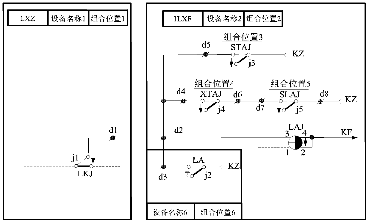
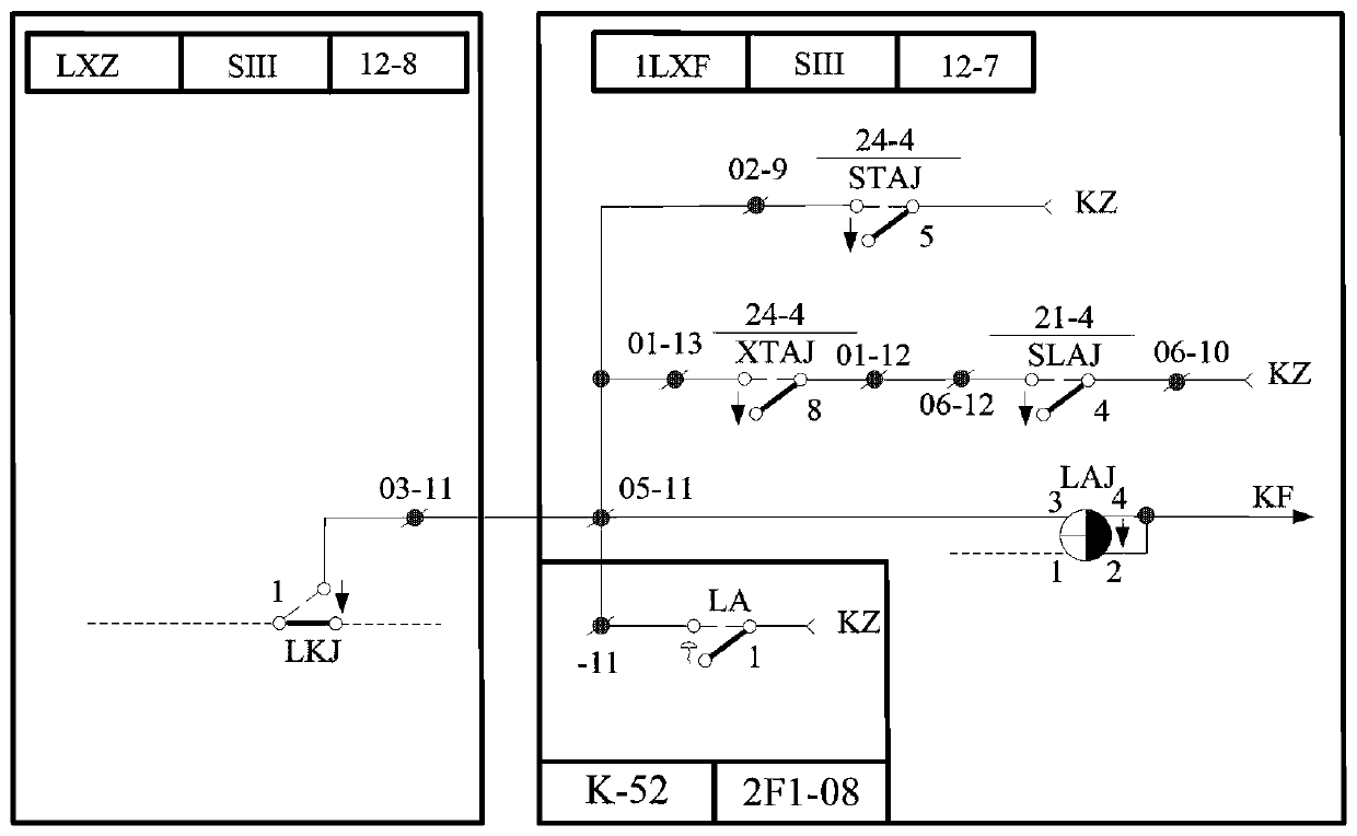
[0030] Such as Figure 1-Figure 3 , The embodiment of the present invention provides a method for wiring the side terminals of the railway signal circuit assembly frame, which is realized by the secondary development of CAD software. The CAD software used in this embodiment is AutoCAD, and the circuit template diagram is drawn in AutoCAD first. , Carry out related operations on the basis of the circuit template diagram, specifically, base...


PUM


Abstract

The invention provides a railway signal circuit combination frame side terminal wiring method, which is realized by performing secondary development on CAD (Computer Aided Design) software. The neuralnetwork method comprises the following steps: drawing a signal circuit template graph in CAD, and performing the following operations on the basis: S1, compiling a man-machine conversation designatedcable wiring connection relation module; S2, compiling various circuit wiring terminal distribution program modules; S3, compiling an actual circuit diagram generation program module; S4, compiling an application program module for extracting wiring information from the actual circuit diagram; S5, compiling a side terminal wiring application program module of the combination frame; S6, compilinga BIM interface module; and S7, compiling a menu module. According to the invention, an actual circuit diagram of a signal is strictly designed; and extracting wiring connection relation data from theactual circuit diagram to design the normal sequence design of the wiring diagram, and outputting a design result that each connecting line of the circuit diagram and each wiring line in the wiring diagram have a one-to-one correspondence relationship, thereby facilitating drawing audit, on-site installation and debugging of equipment and daily operation and maintenance.

Description

Technical field [0001] The invention relates to the field of railway signals, in particular to a method for wiring side terminals of a railway signal circuit assembly frame. Background technique [0002] At present, the wiring of the side terminals of the circuit assembly frame in the railway signal engineering design CAD software is generally not directly taken from the specific signal equipment circuit diagram, but from the pre-defined wiring data sheet. The design result is only the signal equipment finalized circuit layout or general schematic diagram. And circuit terminal wiring diagrams, there is no actual circuit diagram for specific signal equipment. When the diagrams are inconsistent due to errors in the finalized circuit layout and the predefined wiring data sheet during routine maintenance, it is not easy to be found, which is not conducive to the review of the drawings; Often due to the negligence of the designer or the ignorance of the error in the pre-defined databa...

Claims


Application Information

Patent Timeline
Patent Type & Authority Applications(China)
IPC IPC(8): G06F17/50
Inventor 项守宽李乾社
Owner CHINA RAILWAY SIYUAN SURVEY & DESIGN GRP
Why Eureka
Try Eureka