
X-ray flat panel detector and preparation method thereof

A flat-panel detector and X-ray technology, applied in the field of X-ray detectors, can solve the problems of reducing the spatial resolution of the detector and image blurring, and achieve the effects of improving reliability, prolonging life, and improving package sealing

Active Publication Date: 2019-05-03
SHANGHAI IRAY TECH
View PDF6 Cites 2 Cited by
  • Summary
  • Abstract
  • Description
  • Claims
  • Application Information

AI Technical Summary

Problems solved by technology

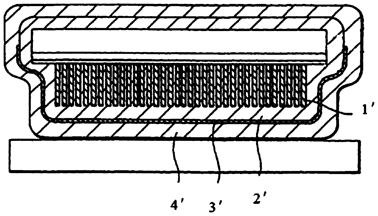
The scintillator layer is usually made of thallium-doped cesium iodide, but cesium iodide is very easy to absorb water vapor in the air and deliquesces. After deliquescence, cesium iodide reduces the spatial resolution of the detector and causes image blur

Method used


Image

  • X-ray flat panel detector and preparation method thereof
  • X-ray flat panel detector and preparation method thereof
  • X-ray flat panel detector and preparation method thereof

Examples


Embodiment 1

[0058] Such as Figure 3-12 As shown, this embodiment provides an X-ray flat panel detector using a Frit-packaged scintillator and a preparation method thereof.

[0059] Such as Figure 9As shown, the present invention provides an X-ray flat panel detector. The X-ray flat panel detector includes a substrate 11 , a reflection layer 12 , a Frit packaging layer 13 , a scintillator layer 14 , an adhesive layer 15 , and a visible light sensor 16 . Specifically, the substrate is provided with a non-encapsulation area 111 and an encapsulation area 112 surrounding the non-encapsulation area, the reflective layer 12 is deposited on the substrate 11, and the Frit encapsulation layer 13 is formed on the reflective layer corresponding to the substrate encapsulation area 112 12; the scintillator layer 13 is formed on the reflective layer 12 corresponding to the non-encapsulation area 111 of the substrate; the adhesive layer 15 covers the surface of the visible light sensor 16 correspondi...

Embodiment 2

[0087] The technical solution of this embodiment is basically the same as that of Embodiment 1, except that this embodiment also includes a step of coating the Frit encapsulation layer multiple times—pre-sintering.

[0088] Specifically, after the Frit encapsulation layer is coated, pre-sintering is performed, and after cooling to room temperature, the Frit encapsulation layer is coated and then pre-sintered. As above, the step of coating the Frit encapsulation layer—pre-sintering is repeated one or more times to obtain Frit encapsulation layers with different thicknesses. This method is also conducive to the smooth discharge of gas generated by the decomposition of organic matter in the Frit encapsulation layer.

[0089] Through this embodiment, the packaging and airtightness of the X-ray flat panel detector can be improved, the reliability in a high-temperature and high-humidity environment can be improved, and the service life can be prolonged.

[0090] To sum up, the X-ra...


PUM


Abstract

The invention provides an X-ray flat panel detector and a preparation method thereof. The X-ray flat panel detector includes a substrate including a non-encapsulation region and an encapsulation region surrounding the non-encapsulation region, a reflective layer applied to a lower surface of the substrate, a Frit encapsulation layer formed on the reflective layer corresponding to the encapsulationregion of the substrate, a scintillator layer formed on the reflective layer corresponding to the non-encapsulation area of the substrate, an adhesive layer covering the surface of a visible lightsensor, and the visible light sensor located on the Frit encapsulation layer and is parallel to the substrate, wherein the Frit encapsulation layer encapsulates the scintillator layer in a sealed cavity composed of the substrate and the visible light sensor. The scintillator layer is encapsulated through the Frit encapsulation layer, the encapsulation sealing of the X-ray flat panel detector is improved, the reliability under high temperature and high humidity conditions is improved, and the service life is prolonged.

Description

technical field [0001] The invention relates to an X-ray detector, in particular to an X-ray flat-panel detector using a Frit packaged scintillator and a preparation method thereof. Background technique [0002] Flat panel detector digital imaging is a new type of ray nondestructive testing technology developed in the late 1990s. As the most advanced digital imaging technology at present, the flat panel detector has many advantages, such as no edge geometric distortion, convenient and reliable storage, large dynamic range and imaging area, high sensitivity and resolution, high detection efficiency of two characters, low system noise, application Flexible and real-time imaging, etc. It is currently the only technology that can replace traditional film photography, and it has been gradually applied in the field of industrial non-destructive testing in recent years. [0003] The X-ray flat panel detector usually includes a visible light sensor and a scintillator layer, wherei...

Claims


Application Information

Patent Timeline
Patent Type & Authority Applications(China)
IPC IPC(8): H01L27/146H01L31/0203
Inventor 杨华
Owner SHANGHAI IRAY TECH
Learn More