
Wireless charging device for water surface robot

A surface robot, wireless charging technology, applied in circuit devices, electrical components, etc., can solve the problems of easy corrosion and disconnection, limit the volume and power consumption of electronic equipment, and large battery volume and weight, so as to overcome the underwater environment. The effect of improving the power transmission efficiency and optimizing the coupling coefficient

Inactive Publication Date: 2019-05-03
HANGZHOU DIANZI UNIV
View PDF5 Cites 1 Cited by
  • Summary
  • Abstract
  • Description
  • Claims
  • Application Information

AI Technical Summary

Problems solved by technology

The modern power transmission method is mainly based on contact power supply. If it is applied underwater, it will have certain disadvantages: the contact head is unreliable, easy to be corroded and disconnected; the various devices are not insulated from each other, and the failure of one device will cause The failure of the entire system; the strength of the wire is low, and it is easy to break under the washing of sea water; the position of the joint is fixed, and the deployment position of the equipment is not flexible
In order to ensure that the underwater sensor has a long enough working life, the battery it carries is large in size and weight, occupying a large amount of internal space in the device, limiting the size and power consumption of the main internal electronic devices, and requiring manual salvage to replace the battery, resulting in additional maintenance costs

Method used


Image

  • Wireless charging device for water surface robot
  • Wireless charging device for water surface robot
  • Wireless charging device for water surface robot

Examples


Embodiment Construction

[0035] In order to make the object, technical solution and advantages of the present invention clearer, the present invention will be further described in detail below in conjunction with the accompanying drawings and embodiments. It should be understood that the specific embodiments described here are only used to explain the present invention, not to limit the present invention.

[0036] On the contrary, the invention covers any alternatives, modifications, equivalent methods and schemes within the spirit and scope of the invention as defined by the claims. Further, in order to make the public have a better understanding of the present invention, some specific details are described in detail in the detailed description of the present invention below. The present invention can be fully understood by those skilled in the art without the description of these detailed parts.

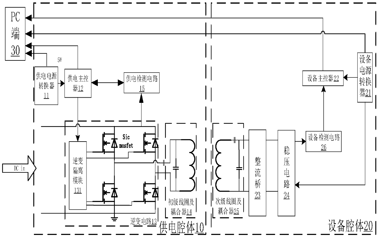
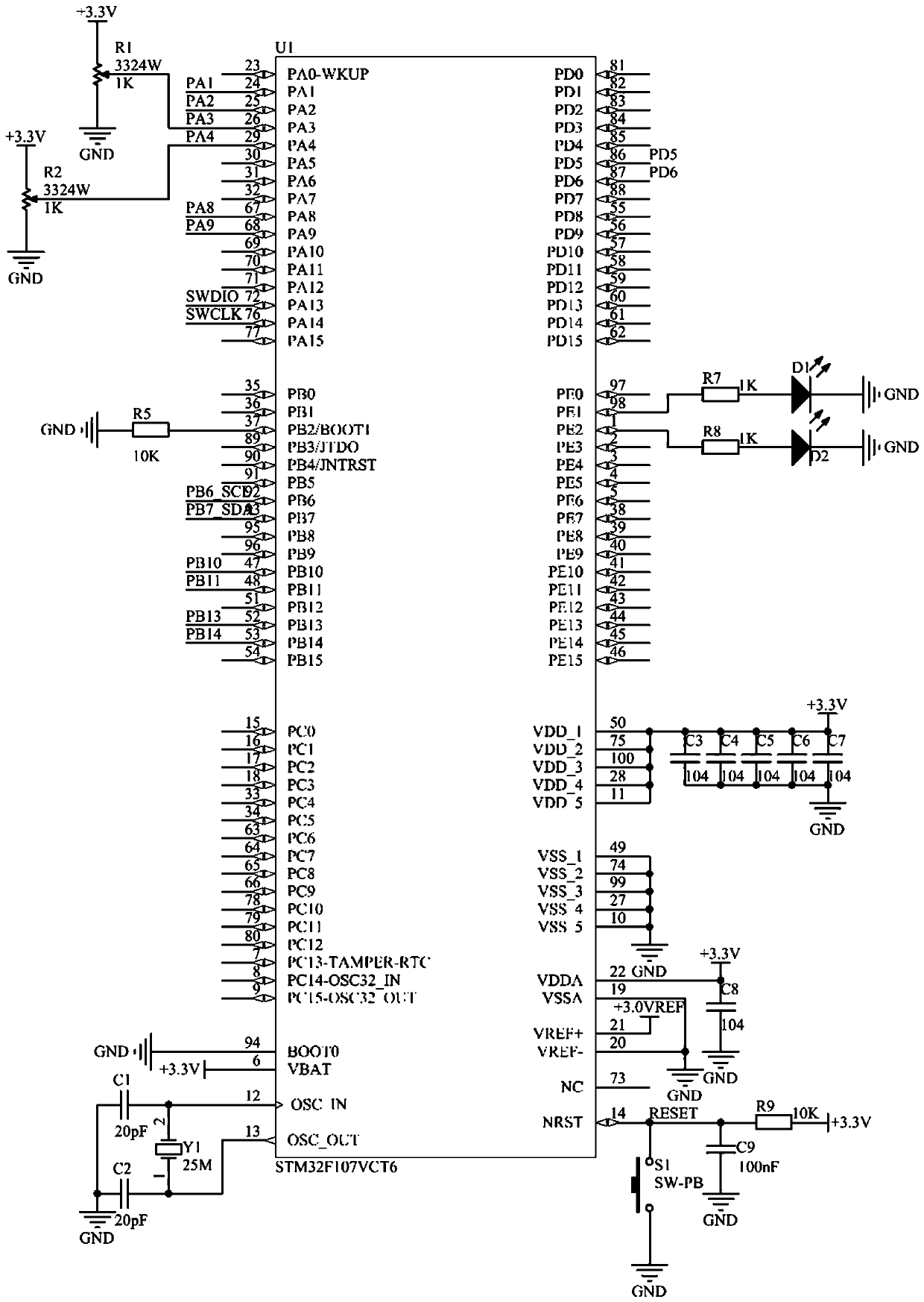
[0037] see Figure 1-12 , including a power supply cavity 10 and a device cavity 20, wherein the powe...


PUM


Abstract

The invention discloses a wireless charging device for a water surface robot. A power supply converter supplies power to a power supply main controller, an inversion circuit and a power supply detection circuit, wherein the inversion circuit comprises an inversion isolation module and four SiCMOSFET full-bridge circuits. The output of the inversion circuit is connected with a primary coil and a coupler, so as to carry out wireless energy transmission on an equipment cavity. The power supply detection circuit detects a voltage, a current and the temperature of the inversion circuit and feeds back the voltage, the current and the temperature to the power supply main controller. The equipment power converter supplies power to the equipment main controller, a voltage stabilizing circuit and anequipment detection circuit. A secondary coil and a coupler receive energy transmitted by the primary coil and the coupler and then the energy is used for charging a load after passing through a rectifier bridge and the voltage stabilizing circuit. The equipment detection circuit detects the voltage, current and working temperature outputted by the voltage stabilizing circuit and feeds back the voltage, current and working temperature to the equipment main controller. Non-contact electric energy transmission is realized, the inversion circuit is high in efficiency, and the charging efficiencyis improved.

Description

technical field [0001] The invention belongs to the field of electronic circuits and relates to a wireless charging device for a surface robot. Background technique [0002] The ocean is a huge treasure house of resources. Under the situation of the depletion of land resources, the space and resources of the ocean have great potential for development. Underwater robots are an important part of it. For underwater equipment to work normally, a stable power supply is first required to solve the problem of power supply. In the traditional contact power transmission, the equipment is connected by wires, and multiple wired plugging and unplugging will damage the waterproof and airtightness of the underwater robot interface. It takes a lot of time to invest in the structural maintenance of the underwater robot. The application of wireless charging has greatly helped and improved these aspects of underwater robots (structural sealing, waterproofing, maintenance), which is conduciv...

Claims


Application Information

Patent Timeline
Patent Type & Authority Applications(China)
IPC IPC(8): H02J50/10
Inventor 李芙蓉史剑光于海滨彭时林周巧娣
Owner HANGZHOU DIANZI UNIV
Learn More