
Photovoltaic charging device for new energy vehicles and charging method thereof

A new energy vehicle and charging device technology, applied in electric vehicle charging technology, photovoltaic power generation, circuit devices, etc., can solve the problems of narrow roads reserved in the charging area, imbalanced charging pile ratio, poor vehicle skills, etc. Stable impact, increased automation, reduced risk effects

Active Publication Date: 2021-05-25
徐州锐德沃汽车科技有限公司
View PDF0 Cites 0 Cited by
  • Summary
  • Abstract
  • Description
  • Claims
  • Application Information

AI Technical Summary

Problems solved by technology

[0002] Practical problems such as environmental pollution and shortage of available resources have led to the focus on new energy-related industries. The main causes of environmental pollution are dust emissions from industrial fuels and exhaust emissions from motor vehicles. Therefore, automakers have begun to develop new energy vehicles. , so with the increase of new energy vehicles, public charging piles have also begun to increase, and the number of related supporting charging infrastructure has also begun to increase, but the ratio of new energy vehicles to their charging piles is seriously out of balance
[0003] Existing charging equipment basically uses a separate mains power as the charging source for charging. In essence, the mains electricity still uses fossil fuels to burn and convert it into electric energy. In fact, it can only play a role in slowing down the protection of the environment and resource consumption. The existing technology Charging equipment requires the driver to open the electric vehicle to the designated area before charging can be carried out. Generally, the road reserved in the charging area is relatively narrow. For those with poor driving skills or novices, it is difficult and may be scratched. Other vehicles are dangerous

Method used


Image

  • Photovoltaic charging device for new energy vehicles and charging method thereof
  • Photovoltaic charging device for new energy vehicles and charging method thereof
  • Photovoltaic charging device for new energy vehicles and charging method thereof

Examples


Embodiment Construction

[0025] After the research and analysis of the applicant, the charging equipment in the prior art basically uses a separate mains power as the charging source. In essence, the mains power still uses fossil fuels to burn and convert it into electric energy. In fact, it can only play a role in environmental protection and resource consumption. The effect of slowing down, the charging equipment of the prior art needs the driver to open the electric vehicle to the designated area before charging can be carried out. Generally, the road reserved in the charging area is relatively narrow. Difficulty, it is possible to bump into other vehicles, which is dangerous. According to these problems, the applicant proposed a photovoltaic charging device for new energy vehicles, the specific scheme is as follows.

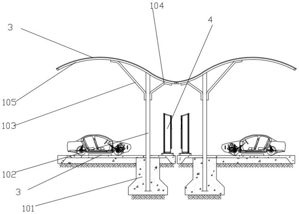
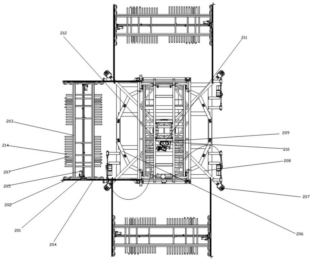
[0026] A photovoltaic charging device for new energy vehicles includes a photovoltaic carport 1, a vehicle mobile device 2, a wireless charging unit 3 and a charging pile 4; the vehi...


PUM


Abstract

The invention discloses a photovoltaic charging device for a new energy vehicle and a charging method thereof, wherein a photovoltaic charging device for a new energy vehicle comprises, by arranging a solar charging unit on the photovoltaic carport, converting solar energy into electric energy to charge an electric vehicle , solar energy does not pollute the environment and reduce environmental pollution. By setting photovoltaic energy storage units as backup power, the backup power can be improved for cloudy and rainy days without the sun, and normal charging can be performed. Electric vehicles can be transported automatically through vehicle mobile devices To the interior of the photovoltaic carport, the automation level of the photovoltaic charging device is improved, which further reduces the instability caused by the driver's parking and reduces the occurrence of danger.

Description

technical field [0001] The invention relates to a photovoltaic charging device for a new energy vehicle, in particular to a photovoltaic charging device for a new energy vehicle and a charging method thereof. Background technique [0002] Practical problems such as environmental pollution and shortage of available resources have led to the focus on new energy-related industries. The main causes of environmental pollution are dust emissions from industrial fuels and vehicle exhaust emissions. Therefore, automakers have begun to develop new energy vehicles. Therefore, with the increase of new energy vehicles, public charging piles have also begun to increase, and the number of related supporting charging infrastructure has also begun to increase, but the ratio of new energy vehicles to their charging piles is seriously out of balance. [0003] Existing charging equipment basically uses a separate mains power as the charging source. In essence, the mains electricity still uses ...

Claims


Application Information

Patent Timeline
Patent Type & Authority Patents(China)
IPC IPC(8): B60L53/30B60L53/38B60L53/51B60L53/53H02S20/23H02S20/26H02J7/35E04H1/12
CPCB60L53/30B60L53/38B60L53/51B60L53/53E04H1/1205H02J7/35H02S20/23H02S20/26Y02B10/10Y02E10/50Y02T10/70Y02T10/7072Y02T10/92Y02T90/12
Inventor 张彦磊
Owner 徐州锐德沃汽车科技有限公司
Learn More