Illumination source for an inspection apparatus, inspection apparatus and inspection method

A technology for inspection equipment and irradiation sources, applied in X-ray equipment, optomechanical equipment, microlithography exposure equipment, etc., and can solve problems such as difficulty in achieving surface flatness

Active Publication Date: 2019-05-03
ASML NETHERLANDS BV
View PDF16 Cites 3 Cited by
  • Summary
  • Abstract
  • Description
  • Claims
  • Application Information

AI Technical Summary

Problems solved by technology

Tilt errors are particularly problematic in the soft X-ray region because the surface flatness of an optical surface is described in terms of the wavelength of radiation incident on the surface; it is much more difficult to achieve acceptable surface flatness for smaller wavelengths

Method used


Image

  • Illumination source for an inspection apparatus, inspection apparatus and inspection method
  • Illumination source for an inspection apparatus, inspection apparatus and inspection method
  • Illumination source for an inspection apparatus, inspection apparatus and inspection method

Examples


Embodiment Construction

[0025] Before describing embodiments of the invention in detail, it is instructive to demonstrate an exemplary environment in which embodiments of the invention may be implemented.

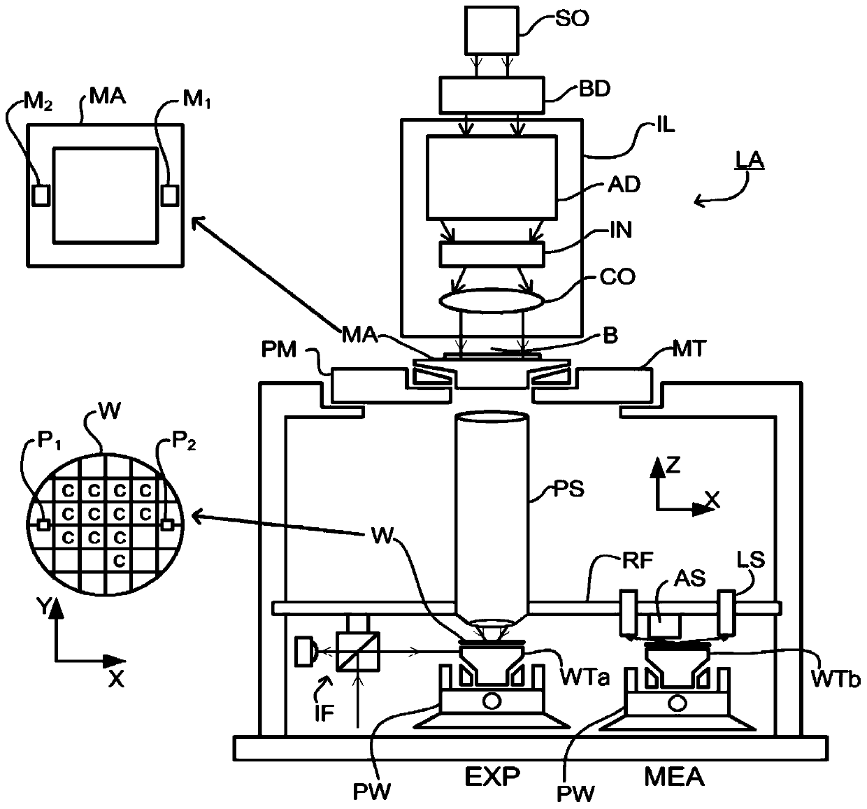
[0026] figure 1 A lithographic apparatus LA is schematically depicted. The apparatus comprises an illumination system (illuminator) IL configured to condition a radiation beam B (e.g. UV radiation or DUV or EUV radiation), configured to support a patterning device (e.g. a mask) MA and connected to a Parameters A patterning device mount or support structure (e.g., a mask stage) MT of a first positioner PM for precisely positioning the patterning device; each configured to hold a substrate (e.g., a resist-coated wafer) W and two substrate handling stages (e.g., wafer handling stages) WTa and WTb each connected to a second positioner PW configured for precisely positioning the substrate according to certain parameters; MA imparts a pattern of radiation beam B projected onto a projection system (eg...


PUM


Abstract

Disclosed is an inspection apparatus and associated method for measuring a target structure on a substrate. The inspection apparatus comprises an illumination source for generating measurement radiation; an optical arrangement for focusing the measurement radiation onto said target structure; and a compensatory optical device. The compensatory optical device may comprise an SLM operable to spatially modulate the wavefront of the measurement radiation so as to compensate for a non-uniform manufacturing defect in said optical arrangement. In alternative embodiments, the compensatory optical device may be located in the beam of measurement radiation, or in the beam of pump radiation used to generate high harmonic radiation in a HHG source. Where located in the beam of pump radiation, the compensatory optical device may be used to correct pointing errors, or impart a desired profile or varying illumination pattern in a beam of the measurement radiation.

Description

[0001] Cross References to Related Applications [0002] This application claims priority to EP application 16188816.9 filed on September 14, 2016 and which application is hereby incorporated by reference in its entirety. technical field [0003] The invention relates to a lithographic apparatus and a method for performing measurements. In particular, it relates to an inspection apparatus comprised in a lithographic apparatus, and in particular an illumination source thereof, and a method for performing measurements therewith. Background technique [0004] A lithographic apparatus is a machine that applies a desired pattern onto a substrate, typically onto a target portion of the substrate. A lithographic apparatus may be used, for example, in the manufacture of integrated circuits (ICs). In this case, a patterning device, alternatively called a mask or reticle, may be used to create the circuit pattern to be formed on the individual layers of the IC. The pattern can be ...

Claims


Application Information

Patent Timeline
Patent Type & Authority Applications(China)
IPC IPC(8): G01N21/95G03F7/20
CPCG01N21/9501G03F7/70616G01N2021/95676H05G2/00G01N21/8806H05G2/008G03F7/70141G03F7/7065
Inventor P·D·范福尔斯特林楠S·B·鲁博尔S·G·J·马斯杰森S·T·范德波斯特
Owner ASML NETHERLANDS BV
Why Eureka
Try Eureka