Automatic unpacking device for injector and using method

A syringe and automatic technology, which is applied in the field of nursing pharmacy liquid preparation and medical care, can solve the problems of cumbersomeness and the inability to improve the efficiency of dispensing, so as to save the cumbersome process, shorten the time of first aid and dressing change, and improve the efficiency of dressing change Effect

Pending Publication Date: 2019-05-07
高佳伟
0 Cites 2 Cited by

AI-Extracted Technical Summary

Problems solved by technology

Although the packaging of disposable syringes is easy to tear, it still requires frequent and cumbersome operations to co...

Abstract

The invention relates to an automatic unpacking device for an injector. The device comprises an operation table, the operation table is provided with a conveying mechanism, an unpacking mechanism, a discharge mechanism and a falling mechanism. A needle receiving box is arranged below the output end of the conveying mechanism, the input end of the conveying mechanism is provided with the dischargemechanism, the unpacking mechanism and the falling mechanism are arranged above the input end of the conveying mechanism, and one side of the input end of the conveying mechanism is provided with a collection barrel. The invention provides a matched using method on the basis. The device has the beneficial effects that the tedious operation process of manual operation is omitted, the problem of bacteria breeding caused by manual operation is solved, the medicine changing efficiency is improved, and rescue and medicine changing time is shortened.

Application Domain

Article unpacking

Technology Topic

InjectorEngineering +1

Image

  • Automatic unpacking device for injector and using method
  • Automatic unpacking device for injector and using method
  • Automatic unpacking device for injector and using method

Examples

  • Experimental program(1)

Example Embodiment

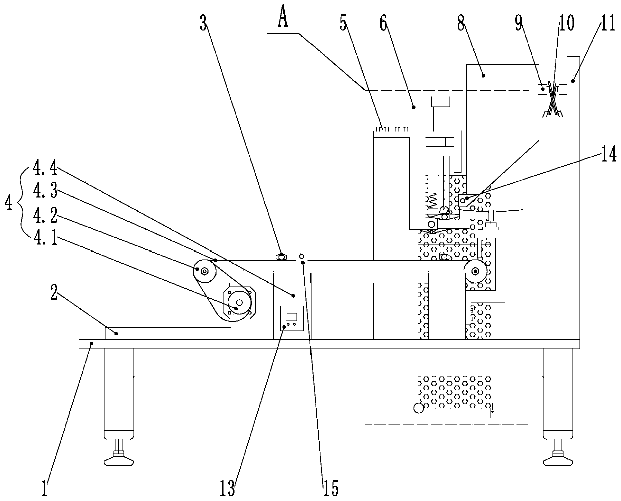
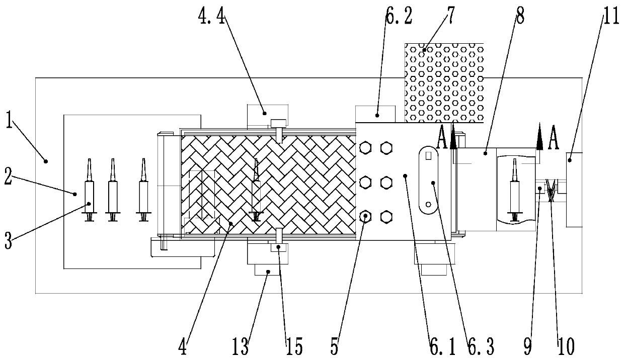
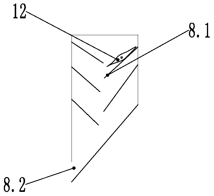
[0042] In the description of the present invention, unless expressly stipulated and limited otherwise, the terms "disposed", "connected", "connected", and "fixed" shall be interpreted broadly. For example, it may be a fixed connection or a fixed connection. The connection can be disassembled or integrated; it can be mechanical connection or electrical connection; it can be directly connected or indirectly connected through an intermediate medium, and it can be the internal communication of two components or the interaction relationship between two components. For those of ordinary skill in the art, the specific meaning of the above-mentioned terms in the present invention can be understood under specific circumstances. In order to clearly illustrate the technical characteristics of the solution, the solution will be described below with reference to the drawings and specific implementations. Take the front of the A4 paper card as the viewing direction, and refer to the attached picture for the corresponding direction.
[0043] Reference attached Figure 1-10 , A specific embodiment of a syringe automatic unpacking device and method of use: comprising an operating table 1, on which a conveying mechanism 4, an unpacking mechanism 6, a discharging mechanism and a discharging mechanism are arranged, and the conveying mechanism 4 A needle box 2 is provided below the output end of the transport mechanism 4, a discharging mechanism is provided at the input end of the conveying mechanism 4, and an unpacking mechanism 6 and a discharging mechanism are respectively provided above the input end of the conveying mechanism 4. A collecting cylinder 7 is provided on one side of the input end of 4. Manually put a plurality of disposable packaged syringes 12 into the unloading mechanism, and send the packaged syringe 12 to the unpacking mechanism 6 through the unloading mechanism. After the unpacking mechanism 6 breaks the bag, the syringe 12 falls to the conveying mechanism 4, and the conveying mechanism 4 The syringe is sent to the needle receiving box 2, and the discharging mechanism discharges the packaging bag of the syringe 12 to the collection cylinder 7, completing the collection process of the packaging bag.
[0044] Reference attached Figure 4 The collection cylinder 7 has a rectangular cylindrical structure, and the top and bottom are respectively provided with a collection port 7.1 and a bottom cover 7.3. The bottom cover 7.3 is hinged to the cylinder body of the collection cylinder 7 through a bottom cover hinge 7.5. The cylinder is provided with a through hole 7.2 and an observation window 7.6, and the bottom cover 7.3 is provided with a bottom cover pin 7.4 that is clamped with the cylinder. It is convenient for the collection tube 7 to recover and observe the collection of the packaging bag, and the bottom cover is movably set to facilitate cleaning.
[0045] Reference attached Figure 1-2 The conveying mechanism 4 includes a conveying motor 4.1, a roller 4.2, a flat belt 4.3, and a conveyor belt support frame 4.4. The conveyor belt support frame 4.4 is arranged on the surface of the operating table 1 and supports the conveying motor 4.1 and the roller 4.2 Flat belt 4.3, the conveyor belt support frame 4.4 is provided with a controller 13 and a counter sensor 15 located on both sides of the flat belt 4.3 driven by the roller 4.2. The conveying mechanism 4 can realize aseptic conveying and collection.
[0046] Reference attached Figure 5 , The unpacking mechanism 6 includes an unpacking mechanism support 6.1, an unpacking mechanism bracket 6.2, an electric push rod 6.3, a push rod connecting block 6.4, a pressure rod 6.5, a pressure rod spring 6.5.1, a pressure block 6.5.2, a cut The knife 6.6, the support plate 6.7 and the support plate spring 6.7.1, the unpacking mechanism bracket 6.2 is arranged on the table of the operating table 1 and on the same side as the collecting cylinder 7, and the unpacking mechanism bracket 6.2 is inverted "L" And support the unpacking mechanism support 6.1. The top surface of the unpacking mechanism support 6.1 is provided with the electric push rod 6.3 and inside is provided with a space for reciprocating movement of the electric push rod 6.3. The push rod end of the rod 6.3 is provided with a push rod connecting block 6.4, the push rod connecting block 6.4 is respectively fixed with a pressure rod 6.5 and a cutter 6.6, the pressure rod 6.5 ends are sequentially fixed with a pressure rod spring 6.5. 1 and pressing block 6.5.2, the bottom of the unpacking mechanism support 6.1 is provided with an extended end supporting the pressing block 6.5.2, and the support plate 6.7 is hinged on the extended end, and the bottom surface of the support plate 6.7 A support plate spring 6.7.1 is fixedly connected to the bottom surface of the extension end, and the support plate spring 6.7.1 supports the support plate 6.7. The disposable syringe package can be automatically opened, eliminating the tedious process of manual operation and eliminating the undesirable factors of manual operation.
[0047] Reference attached Figure 5 , The discharging mechanism includes a stepping motor 6.8, a straight blade stirring impeller 6.8.1, a baffle 6.8.2, and a motor bracket 6.8.3, the motor bracket 6.8.3 is fixedly connected to the input end of the conveying mechanism 4 Between the conveyor belt support frames 4.4 on both sides, the motor support 6.8.3 has an inverted "C" shape and the opening points to the input end of the conveying mechanism 4, and the motor support 6.8.3 is provided with the stop at the opening. Plate 6.8.2, the baffle 6.8.2 is located above the roller 4.2, the top surface of the motor support 6.8.3 is provided with a stepping motor 6.8, and the rotating shaft of the stepping motor 6.8 is fixed with a straight blade stirring The impeller 6.8.1, the bottom surface of the straight blade stirring impeller 6.8.1 is higher than the top surface of the support plate 6.7 by 2 mm, and the straight blade stirring impeller 6.8.1 extends to the center position of the support plate 6.7. The packaging bag of the syringe 12 is discharged to the collection tube 7 through the straight blade stirring impeller 6.8.1 of the discharging mechanism, and the collection process of the packaging bag is completed.
[0048] The number of blades of the straight blade stirring impeller 6.8.1 is two. The straight blade stirring impeller 6.8.1 with two blades is adopted, and the blades are parallel to the cutter 6.6 in the initial state; Figure 5 , The straight-blade stirring impeller 6.8.1 returns to its original state after one rotation. This setting mode can discharge the packaging bag while preventing the blade from blocking the packaging syringe 12 from falling to the inner wall of the mechanism support 6.1.
[0049] Reference attached Figure 5 The unloading mechanism includes a lower hopper 8, an electromagnetic vibrator 9, a plate spring 10, and a vibrating machine bracket 11. The vibrating machine bracket 11 is vertically arranged on the table at the end of the operating table 1 and the top end is directly opposite to the A lower hopper 8, an electromagnetic vibrator 9 and a leaf spring 10 are sequentially fixed in the direction of the unpacking mechanism 6. The bottom of the lower hopper 8 is provided with a discharge port 8.2, and the opening of the discharge port 8.2 faces the cutter 6.6 On the bottom edge, photoelectric switches 14 are provided on both sides of the discharge port 8.2 in the discharge direction. The lower hopper 8 is provided with several pouring plates 8.1 which are relatively staggered and inclined downward. The photoelectric switch 14, the feeder 8.1, and the vibrating feeding method facilitate the intermittent drop of the packaged syringe 12.
[0050] Reference attached Figure 8-9 , The number of the cutter 6.6 is two and the end of the cutter 6.6 is an arc-shaped cut 6.6.1. The length of the cutter 6.6 is W, the length of the package syringe 12 is W1, where W is greater than W1; the width of the cutter 6.6 is H, and the width of the syringe 3 is H1, where H is greater than H1; the cutter 6.6 The size setting method prevents damage to the syringe while cutting the bag.
[0051] Reference attached Picture 10 The controller 13 is electrically connected to the conveying motor 4.1, the electric push rod 6.3, the stepping motor 6.8, and the electromagnetic vibrating machine 9, respectively. The controller 13 is provided with the driving motor 4.1, the electric push rod 6.3, and the stepping motor. The drive of the motor 6.8 and the electromagnetic vibrating machine 9 can be realized by 51 single-chip microcomputer, and the automatic control is facilitated by the controller 13.
[0052] A method of using automatic unpacking device for syringe, refer to Image 6 , Figure 7 , Attached Picture 10 , The working process of the embodiment:
[0053] S01: Put the packaged syringe 12 into the lower hopper 8;
[0054] S02: Turn on the switch of the controller 13, the electromagnetic vibrator 9 drives the lower hopper 8 to vibrate, and the packaged syringe 12 slides down from the discharge port 8.2 of the lower hopper 8 to the unpacking mechanism support 6.1. The bottom of the support block 6.5.2 is provided. The top surface of the outlet end and abut against the inner wall of the mechanism support 6.1 on the side of the pressing block 6.5.2. When the package syringe 12 slides out from the outlet 8.2 of the lower hopper 8, the outlet 8.2 is provided with a photoelectric switch 14 Trigger the electric push rod 6.3 and the conveying mechanism 4, and control the electromagnetic vibrating machine 9 to close, the electric push rod 6.3 forwards the push rod connecting block 6.4 to drive the fixed pressing rod 6.5 and the cutter 6.6 to move down to complete the pressure cutting The process of packaging the bag and dropping the syringe 3 in the packaging bag onto the flat belt 4.3 of the conveying mechanism 4;
[0055] S03: The conveying mechanism 4 conveys the syringe 3 and passes through the counter sensor 15 on both sides of the flat belt 4.3. The counter sensor 15 triggers the electric push rod 6.3 to reverse and the discharging mechanism stepper motor 6.8 to rotate to discharge the packaging bag to one side of the collection In the barrel 7, while the delivery mechanism 4 finally delivers the syringe 3 to the needle box 2 provided under the output end of the delivery mechanism 4;
[0056] S04: After the stepping motor 6.8 rotates, the electromagnetic vibrating machine 9 is triggered again to work, and the process of step S02 is repeated.
[0057] Of course, the above description is not limited to the above examples. The undescribed technical features of the present invention can be implemented by or using existing technology, and will not be repeated here; the above embodiments and drawings are only used to illustrate the technical solutions of the present invention. It is a limitation of the present invention. Instead, the present invention has only been described in detail with reference to the preferred embodiments. Those of ordinary skill in the art should understand that those of ordinary skill in the art have made it within the essential scope of the present invention. The changes, modifications, additions or substitutions do not depart from the purpose of the present invention, and should also belong to the protection scope of the claims of the present invention.

PUM

no PUM

Description & Claims & Application Information

We can also present the details of the Description, Claims and Application information to help users get a comprehensive understanding of the technical details of the patent, such as background art, summary of invention, brief description of drawings, description of embodiments, and other original content. On the other hand, users can also determine the specific scope of protection of the technology through the list of claims; as well as understand the changes in the life cycle of the technology with the presentation of the patent timeline. Login to view more.

Similar technology patents

Signing method and device for electronic contracts of the same type and storage medium

PendingCN111145054AReduce cumbersome processImprove efficiency
Owner:北京天威诚信电子商务服务有限公司

Transformer with split and pluggable iron core for screening test

InactiveCN106952711AQuick and easy plugging and unpluggingReduce cumbersome process
Owner:WOLONG ELECTRIC GRP CO LTD +1

Method for recommending next user input using pattern analysis of user input

ActiveUS20200134488A1reduce cumbersome process
Owner:SAMSUNG SDS CO LTD

Rubber hose braid processing system and processing technology

ActiveCN111422706AShorten the production and processing cycleReduce cumbersome process
Owner:卓凡液压科技有限公司

Classification and recommendation of technical efficacy words

  • Improve the efficiency of dressing change
  • Reduce cumbersome process

Dressing change vehicle for ophthalmologists

InactiveCN108042299AImprove the efficiency of dressing changeEasy to take medicine or tools
Owner:郝军生

Indoor decoration wall tile laying device

ActiveCN111424935Areduce manual laborReduce cumbersome process
Owner:马鞍山宏合建筑工程有限公司

Method for recommending next user input using pattern analysis of user input

ActiveUS20200134488A1reduce cumbersome process
Owner:SAMSUNG SDS CO LTD

Signing method and device for electronic contracts of the same type and storage medium

PendingCN111145054AReduce cumbersome processImprove efficiency
Owner:北京天威诚信电子商务服务有限公司
Why Eureka
Try Eureka