
Power maintenance lifting device

A lifting device and power maintenance technology, applied in the direction of cranes, etc., can solve the problems of high precision requirements, low precision, and large components of lifting equipment, so as to achieve unaffected transmission effect, easier control of expansion and contraction, and self-locking effect. Good results

Inactive Publication Date: 2019-05-07
STATE GRID SHANDONG ELECTRIC POWER CO BOXING POWER SUPPLY CO
View PDF5 Cites 0 Cited by
  • Summary
  • Abstract
  • Description
  • Claims
  • Application Information

AI Technical Summary

Problems solved by technology

When inspecting and repairing the power supply equipment, in addition to climbing high, the staff also need to disassemble and replace related parts. Some parts are large in size or heavy in weight, and it is very inconvenient to carry them by manpower alone.
Cranes are usually used for equipment hoisting, while the jibs of traditional cranes are mostly driven by hydraulic pressure. Due to the complex distribution of power transmission lines, the precision requirements for lifting equipment are high. Although hydraulic equipment is controllable, the precision is low, and Unable to adapt to complex environmental requirements for power supply equipment maintenance

Method used


Image

  • Power maintenance lifting device
  • Power maintenance lifting device
  • Power maintenance lifting device

Examples


Embodiment 1

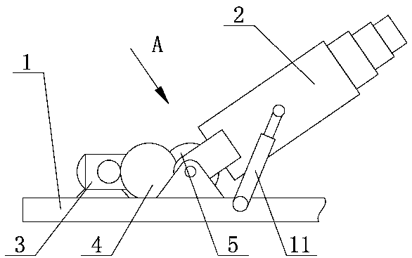
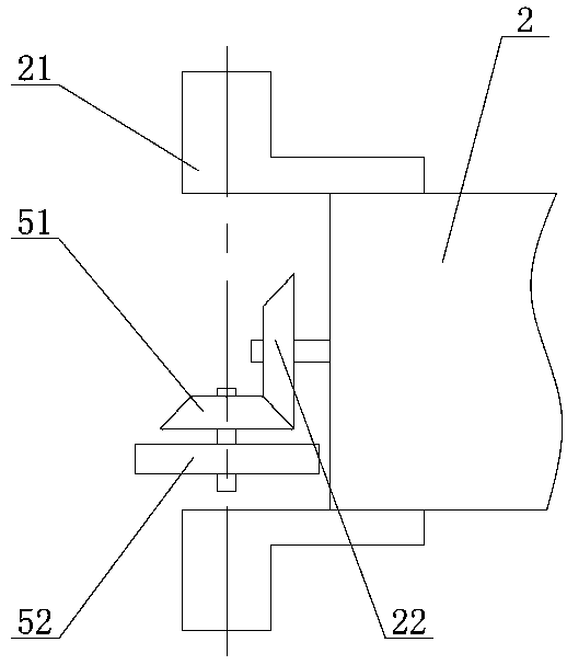
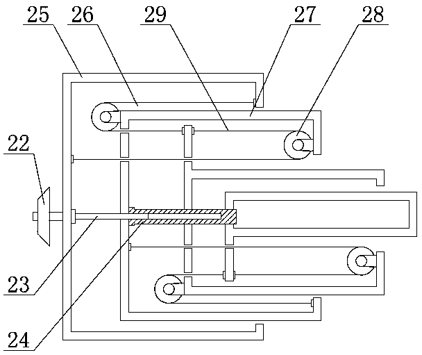
[0025] Such as Figure 1 ~ Figure 3 As shown, a lifting device for electric power maintenance provided by the embodiment of the present invention includes a frame 1, a boom 2 and a motor 3, the boom 2 and the motor 3 are all arranged on the frame 1, and the tail of the boom 2 Rotating parts 21 are arranged on both sides of the end, and the rotating parts 21 are connected to the frame 1 in rotation. There is a space between the rotating parts 21 on both sides. In this space, a reversing device 5 and a first bevel gear 22 are arranged. The reversing device 5 includes a second bevel gear. Bevel gear 51 and driven gear 52, the second bevel gear 51 meshes with the first bevel gear 22, driven gear 52 is connected with motor 3 through reduction gear 4, driven gear 52 is cylindrical gear, driven gear 52 and the second The bevel gear 51 is coaxially fixedly connected and coaxial with the rotation axis of the boom 2 .

[0026] The first bevel gear 22 is arranged at the tail end of the ...

Embodiment 2

[0036] Such as Figure 4 Figure 5 As shown, in this embodiment, the speed reduction device 4 is a planetary speed reducer, the motor 3 is connected to the third bevel gear 53 through the speed reduction device 4, and the third bevel gear 53 is engaged with the second bevel gear 51 for transmission. The other parts of this embodiment are consistent with the implementation Example 1 is basically the same.


PUM


Abstract

The invention relates to the field of power maintenance equipment, in particular to a power maintenance lifting device. The device can improve accuracy in lifting operation. The power maintenance lifting device comprises a rack, a cargo boom and a motor, wherein the tail end of the cargo boom is rotationally connected with the rack, the motor is fixedly connected with the rack, the cargo boom comprises telescopic booms which are sequentially nested from outside to inside, the outermost telescopic boom is the first telescopic boom, the inner side of the first telescopic boom is connected with the second telescopic boom, ..., the inner side of the nth telescopic boom is connected with the (n+1)th telescopic boom, every two adjacent telescopic booms are connected through a transmission device, the first telescopic boom and the second telescopic boom are provided with a lead screw and a sliding sleeve respectively, the sliding sleeve is in threaded connection with the lead screw, one end of the lead screw is located on the outer side of the first telescopic boom, and is provided with a first bevel gear, the lead screw is rotationally connected with the first telescopic boom, the motoris connected with a reversing device, the reversing device comprises a second bevel gear, the first bevel gear is meshed with the second bevel gear, and the second bevel gear is coaxial with a rotating shaft of the cargo boom.

Description

technical field [0001] The invention relates to the field of electric power maintenance equipment, in particular to a lifting device for electric power maintenance. Background technique [0002] Power equipment mainly includes two categories: power generation equipment and power supply equipment, and power supply equipment includes transmission lines of various voltage levels. Most of the transmission lines are set in the air, and the transmission lines used by some power supply facilities are numerous and miscellaneous, criss-crossing in the air. When repairing power supply equipment, in addition to ascending heights, workers also need to disassemble and replace related components. Some components are large in size or heavy in weight, and it is very inconvenient to rely solely on manpower to carry them. Cranes are usually used for equipment hoisting, while the jibs of traditional cranes are mostly driven by hydraulic pressure. Due to the complex distribution of power trans...

Claims


Application Information

Patent Timeline
Patent Type & Authority Applications(China)
IPC IPC(8): B66C23/62B66C23/64B66C23/70
Inventor 兰海张允兵张村崔海平付康
Owner STATE GRID SHANDONG ELECTRIC POWER CO BOXING POWER SUPPLY CO
Learn More