Embroidery machine good in frame movement stability, driving device for frame and bridge auxiliary rail

A stable, embroidery machine technology, applied in the direction of embroidery machine, feeding device, embroidery machine mechanism, etc., can solve the problems that need to be further improved, and achieve the effect of compact structure, small vibration influence, and reduced jitter

Pending Publication Date: 2019-05-07
ZHEJIANG YUELONG SEWING EQUIP
View PDF1 Cites 2 Cited by
  • Summary
  • Abstract
  • Description
  • Claims
  • Application Information

AI Technical Summary

Problems solved by technology

In summary, the movement of the embroidery frame in the X direction will no longer be constrained by the instability of the embroidery frame, but only one end of the suspension rail is connected to the beam, and the stability of the other end depends entirely on the strength of the suspension rail itself and the relationship between the slider and the suspension rail. Therefore, the miniaturization of the volume and the stability of the maximum Y stroke need to be further improved

Method used


Image

  • Embroidery machine good in frame movement stability, driving device for frame and bridge auxiliary rail
  • Embroidery machine good in frame movement stability, driving device for frame and bridge auxiliary rail
  • Embroidery machine good in frame movement stability, driving device for frame and bridge auxiliary rail

Examples


Embodiment 1

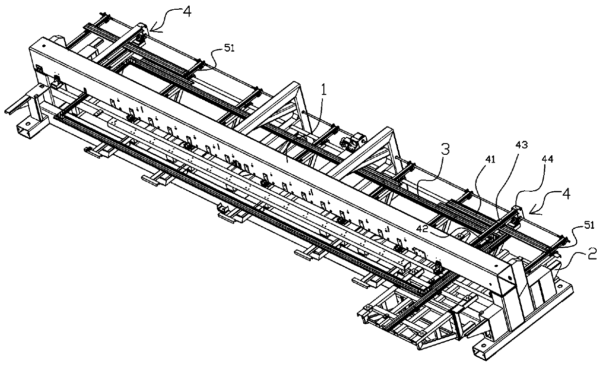
[0037] Such as figure 1 As shown, this embodiment provides an embroidery machine with good frame movement stability, including:

[0038] The frame includes a crossbeam 1 and a frame lower body 2 located below the crossbeam 1; the crossbeam 1 is erected with the frame lower body 2;

[0039] The mobile frame 3 is movably arranged above the lower body 2 of the frame;

[0040] The bridge sub-rail 4 is connected with the moving frame 3 for driving the moving frame 3 to move on the lower body 2 of the frame, and it includes a side end of the moving frame 3 for driving the moving frame 3 The synchronously moving auxiliary rail 41 extending along the first direction, the bridge auxiliary rail driving guide rail 42 located above the auxiliary rail 41 extending along the second direction perpendicular to the first direction, and the auxiliary rail driving guide rail 42 arranged on the bridge auxiliary rail The bridge driving trolley 43 on the guide rail 42 and the bridge auxiliary rai...

Embodiment 2

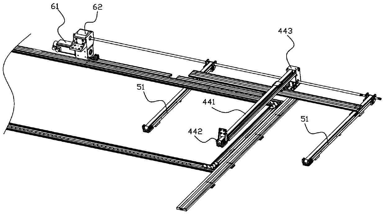
[0051] Such as figure 2 , image 3 , Figure 4 As shown, in this embodiment, the auxiliary rail 4 of the bridge frame cooperates with the Y drive to realize the movement of the moving frame 3 along the Y stroke direction, specifically, as figure 2As shown, the embroidery machine in this embodiment also includes a drive motor 61 and a drive motor transmission box 62 connected to the rotating shaft of the drive motor 61, and the two sides of the bridge sub-rail transmission box assembly 44 are respectively connected to each other by a transmission shaft. A pulley driven by the Y is connected, and a pulley driven by the Y is connected with the drive motor transmission box 62 through a transmission shaft rod, and through the design of the drive motor transmission box 62, the power output of the drive motor 61, Simultaneously act on the belt pulley of bridge auxiliary rail transmission box assembly 44 and Y drive. The above-mentioned design makes it possible to ensure the high...

Embodiment 3

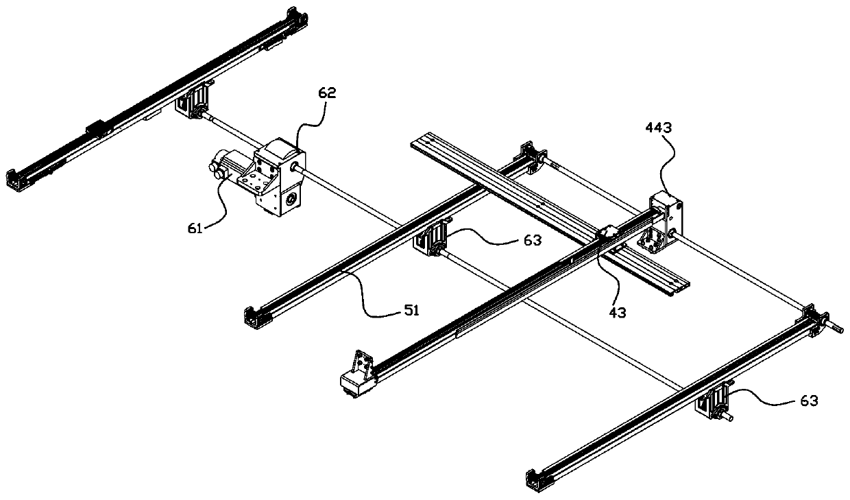
[0067] Such as Figure 5As shown, this embodiment provides a driving device for an embroidery machine frame, including: a Y drive and a bridge sub-rail 4 arranged between the two Y drives, and the bridge sub-rail 4 includes a bridge extending along the first direction. The auxiliary rail 41, the bridge auxiliary rail driving guide rail 42 extending along the second direction perpendicular to the first direction above the auxiliary rail 41, the bridge driving trolley 43 arranged on the bridge auxiliary rail driving guide rail 42 and the The bridge auxiliary rail transmission box assembly 44 used to transmit power to drive the bridge driving trolley 43 to move along the extension direction of the bridge auxiliary rail driving guide rail 42 on the bridge auxiliary rail driving guide rail 42, the bridge driving trolley 43 and the bridge auxiliary rail driving guide rail 42 The center of the auxiliary rail 41 is connected, preferably through a connecting block and the through hole ...


PUM


Abstract

The invention discloses an embroidery machine good in frame movement stability, a driving device for a frame and a bridge auxiliary rail. The embroidery machine comprises the bridge auxiliary rail andY driver; the bridge auxiliary rail comprises an auxiliary rail body extending in the first direction, a bridge auxiliary rail driving guide rail which is located above the auxiliary rail body and extends in the second direction perpendicular to the first direction, a bridge driving trolley which is arranged on the bridge auxiliary rail driving guide rail and a bridge auxiliary rail driving guiderail transmission box assembly arranged on the bridge auxiliary rail driving guide rail, and the bridge driving trolley is connected with the center of a rack; one end of the bridge auxiliary rail driving guide rail is connected with a cross beam through a connecting support assembly, and the other end of the bridge auxiliary rail driving guide rail is connected with the lower portion of the rackthrough the bridge auxiliary rail driving guide rail transmission box assembly; the Y driver comprises a Y drive guide rail which is connected to the lower portion of the rack and extends in the Y axis direction and a Y drive trolley which is driven by a belt pulley and a conveyor belt to be slidably arranged on the Y drive guide rail, and the Y rive trolley is connected with the lower surface ofthe auxiliary rail body. Accordingly, under extra long travel and high rotation speed, good structure and movement stability of the frame can still be kept, vibration is small, frame movement deformation is not likely to be generated, and the embroidery output quality is high.

Description

technical field [0001] The invention relates to the field of embroidery machine drive technology, in particular to an embroidery machine with good frame movement stability, a drive device for the frame, and a bridge auxiliary rail. Background technique [0002] The frame on the embroidery machine is used to fix the fabric of the embroidery. The movement of the frame directly drives the fabric to move, so as to achieve the purpose of embroidery patterns. Therefore, the stability and precision of the movement of the frame directly affect the quality of the embroidery. [0003] Considering the pressure of cost and efficiency, the existing embroidery machines have more and more heads, the rotation speed of the power motor of the embroidery machine is getting higher and higher, and the length of the frame is getting longer and longer. At the same time, the motor vibration and The problems of long moving stroke, poor driving structure strength, and unstable movement have more and ...

Claims


Application Information

Patent Timeline
Patent Type & Authority Applications(China)
IPC IPC(8): D05C9/20D05C9/04D05C9/06D05C9/12D05C9/16
Inventor 陈天池陈天龙张汉苗郑邓飞
Owner ZHEJIANG YUELONG SEWING EQUIP
Why Eureka
Try Eureka