Magnetorheological damper piston assembly with sedimentation active dispersing device

A technology of magnetorheological damper and piston assembly, applied in the direction of shock absorber, shock absorber, spring/shock absorber, etc. The effect of energy recovery

Active Publication Date: 2019-05-07
振声慧源(重庆)科技有限公司
View PDF6 Cites 8 Cited by
  • Summary
  • Abstract
  • Description
  • Claims
  • Application Information

AI Technical Summary

Problems solved by technology

Unfortunately, due to the complexity of the mechanical structure and practical problems in engineering applications, this structure has not been effectively realized so far

Method used


Image

  • Magnetorheological damper piston assembly with sedimentation active dispersing device
  • Magnetorheological damper piston assembly with sedimentation active dispersing device
  • Magnetorheological damper piston assembly with sedimentation active dispersing device

Examples


Embodiment 1

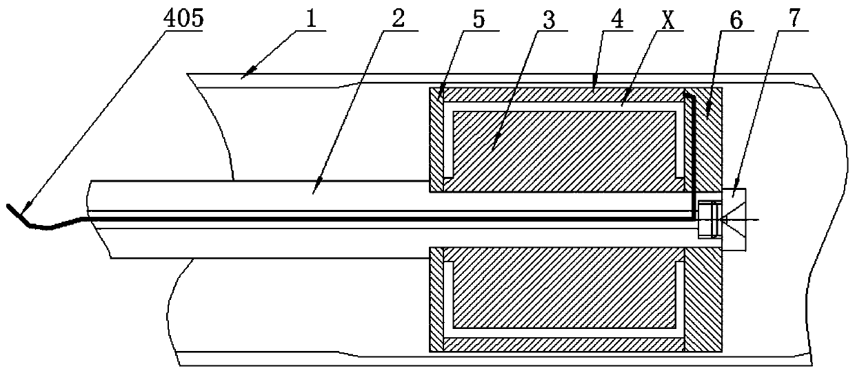
[0045] see figure 1 , a magneto-rheological damper piston assembly with a sedimentation active dispersion device, characterized in that it includes a working cylinder 1, a piston rod 2 and a piston assembly.

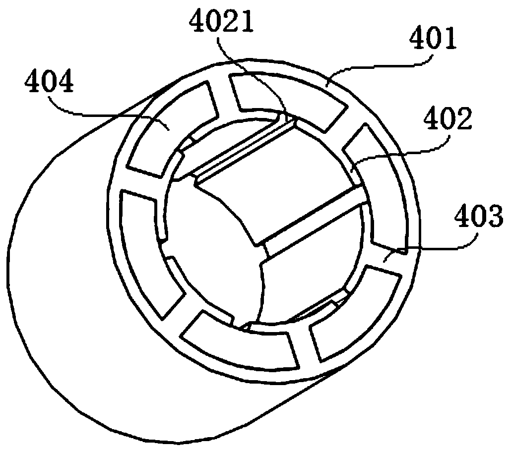
[0046] see Figure 4 , the working cylinder 1 is cylindrical. There are several through grooves I101 and several through holes I102 evenly distributed around the circumference of the working cylinder 1 , wherein the through grooves I101 are located on the inner surface of the working cylinder 1 , and its position is recorded as the balance position of the working cylinder 1 . The working cylinder 1 is filled with magnetorheological fluid.

[0047] see Figure 7 , the piston rod 2 is a hollow cylinder. The inner wall of the upper end of the piston rod 2 is processed with threads. A plurality of lead grooves I201 are opened on the end surface of the upper end of the piston rod 2 . The upper end of the piston rod 2 penetrates the inside of the working cylinder 1, and ...

Embodiment 2

[0070] see figure 1 , a magneto-rheological damper piston assembly with a sedimentation active dispersion device, characterized in that it includes a working cylinder 1, a piston rod 2 and a piston assembly.

[0071] see Figure 4 , the working cylinder 1 is cylindrical. Several through grooves I101 and several through holes I102 are uniformly distributed around the working cylinder 1 , wherein the through grooves I101 are located on the inner surface of the working cylinder 1 , and its position is recorded as the balance position of the working cylinder 1 . The working cylinder 1 is filled with magnetorheological fluid.

[0072] see Figure 7 , the piston rod 2 is a hollow cylinder. The inner wall of the upper end of the piston rod 2 is processed with threads. A plurality of lead grooves I201 are opened on the end surface of the upper end of the piston rod 2 . The upper end of the piston rod 2 penetrates the inside of the working cylinder 1, and can reciprocate inside t...


PUM


Abstract

The invention discloses a magnetorheological damper piston assembly with a sedimentation active dispersing device. The magnetorheological damper piston assembly comprises a working cylinder, a pistonrod and a piston assembly; the working cylinder is internally provided with magnetorheological fluid; the upper end of the piston rod penetrates into the working cylinder, and the part, penetrating out of the working cylinder, of the lower end of the piston rod is provided with an oil seal; the piston assembly includes a rotor, a stator, a top cover and a bottom cover; the outer circumferential wall of the rotor is provided with spiral ribs; the rotor is arranged on the piston rod in a loose sleeving manner and is located inside the working cylinder; the stator is arranged on the rotor in a sleeving manner and is located inside the working cylinder; a damping gap is formed between the stator and the rotor; the top cover is installed on the piston rod in a sleeving manner and is located inthe working cylinder; and the bottom cover is located in the working cylinder. The spiral ribs on the rotor rotate to make the magnetorheological fluid flow in the working cylinder through the dampinggap to do rotating flow and axial flow, redispersion after sedimentation of the magnetorheological fluid is achieved, and energy recovery when a magnetorheological damper normally runs is facilitated.

Description

technical field [0001] The invention relates to the field of magnetorheological dampers, in particular to a magnetorheological damper piston assembly with a settlement active dispersing device. Background technique [0002] Magnetorheological fluid is a suspension formed by mixing tiny soft magnetic particles with high magnetic permeability and low magnetic hysteresis and non-magnetic liquid. This kind of suspension exhibits low-viscosity Newtonian fluid characteristics under the condition of zero magnetic field; while under the action of strong magnetic field, it presents high-viscosity, low-fluidity Bingham fluid characteristics. In the case of zero magnetic field, the magnetorheological fluid behaves as a liquid with good flow performance, and its apparent viscosity is very small; under the action of a strong magnetic field, the apparent viscosity can increase by more than two orders of magnitude in a short time (milliseconds), and presents Solid-like properties; and thi...

Claims


Application Information

Patent Timeline
Patent Type & Authority Applications(China)
IPC IPC(8): F16F9/53F16F9/32F16F9/34F16F9/36
Inventor 张红辉杨涛廖昌荣谢磊
Owner 振声慧源(重庆)科技有限公司
Why Eureka
Try Eureka