Supercharge Your Innovation With Domain-Expert AI Agents!

Non-bevel gear differential

A technology of differentials and bevel gears, which is applied in the field of differentials with non-bevel gear structures, can solve the problems of difficult manufacturing and large volume of planetary gear differentials, and achieve the effects of wide application range, small size and easy manufacturing

Inactive Publication Date: 2019-05-07
罗灿
View PDF0 Cites 0 Cited by
  • Summary
  • Abstract
  • Description
  • Claims
  • Application Information

AI Technical Summary

Problems solved by technology

The planetary gear differential of the bevel gear planetary row is large in size and difficult to manufacture

Method used


Image

  • Non-bevel gear differential
  • Non-bevel gear differential
  • Non-bevel gear differential

Examples


Embodiment 1

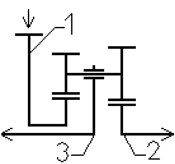
[0016] Embodiment 1: Example 1 of the non-bevel gear differential of the present invention A six-non-bevel gear differential with a single-row variable linear speed planetary row structure is also the embodiment 1 of the present invention. Assume that the ratios of the rotational speed ratio and the torque ratio required by the two output terminals are both 1.0. Embodiment 1 The planetary row structure of the transmission machine is a six-single-row planetary row in the form of a variable linear speed planetary row, and all the planetary rows are gears with parallel teeth and non-bevel gears. Assuming that the number of teeth on the right set of gears of the variable line speed planetary gear is Xy, the number of teeth on the other set of gears on the left is Xz, the number of teeth on the left center gear z is Zz, and the number of teeth on the right center wheel y is Zy, then the variable line speed is defined The characteristic parameter of the planetary row is a, a=(Zy*Xz)...

Embodiment 2

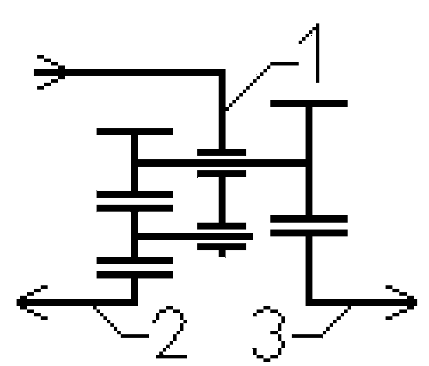
[0017]Embodiment 2: Example 2 of the non-bevel gear differential of the present invention The second non-bevel gear differential is also the embodiment 2 of the present invention. Assume that the ratios of the rotational speed ratio and the torque ratio required by the two output terminals are both 1.0. Embodiment 2 The planetary row structure of the transmission machine is the structural form of the variable linear speed planetary row II single row planetary row, and all the planetary row adopts gears with parallel teeth and non-bevel gear structure. The outer planetary gear on the variable-linear-speed planetary planetary carrier is a variable-linear-speed planetary gear, assuming that the number of teeth of a set of gears on the right side of the variable-linear-speed planetary wheel is Xy, the number of teeth of another set of gears on the left side is Xz, and the center of the left side is The number of teeth of the wheel z is Zz, and the number of teeth of the right cent...

Embodiment 3

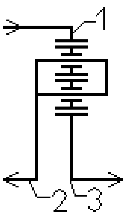
[0018] Embodiment 3: Example 3 of the non-bevel gear differential of the present invention The single-row ordinary double-layer planetary row non-bevel gear differential is also the embodiment 3 of the present invention. Assume that the ratios of the rotational speed ratio and the torque ratio required by the two output terminals are both 1.0. Embodiment 3 The planetary row structure of the transmission machine is an ordinary double-layer planetary row, and all the planetary rows are gears with parallel teeth and non-bevel gear structure. Let the number of teeth of the inner ring gear q be Zq, and the number of teeth of the sun gear be Zt. Then define the characteristic parameter of this variable linear velocity planetary row to be a, a=Zq / Zt, this single-row ordinary double-layer star planetary row obeys its planetary row motion equation and is also its planetary row structural equation Nt-a*Nq-(1- a)*Nj=0, which is Nq-((a-1) / a)*Nj-(1 / a)*Nt=0 after simplification. The coeff...


PUM


Abstract

The invention discloses a non-bevel gear differential. Power can be output to two output ends according to a speed ratio b and a torque ratio 1 / b; transmission machinery is a planet row structure of atwo-degree-of-freedom decision system; a simplified form of a planet row structure equation is N1-k1*N2-k2*N3=0, wherein k1 and k2 are positive numbers; a rotating component corresponding to a rotating speed item N1 is adopted as a power input end; two rotating components corresponding to rotating speed items N2 and N3 are adopted as the power output ends; the rotating speed ratio of the two output ends is set as N2 / N3=b; and the torque ratio is 1 / b. The first condition of the planet row structure as the transmission machinery of the differential is to adjust the values of k1 and k2 to realize k2 / k1=b. The second condition of the planet row structure as the transmission machinery of the differential is that the planet row structure is of a non-bevel gear structure and a gear in the planetrow structure adopts such non-bevel gear tooth forms as a parallel gear tooth form.

Description

technical field [0001] The invention relates to a planetary gear differential, in particular to a non-bevel gear differential with two degrees of freedom determining the planetary row structure of the system. Background technique [0002] During the driving process of the motor vehicle, due to the reason of turning, due to the difference of the road surface, and due to the difference of the wheels of the vehicle, the rotational speeds of the driving paths will not be exactly the same. The exact same rotation speed of each driving path will cause wheel slip and slip, which will make the vehicle control malfunction. Traditional motor vehicles adapt to this difference in speed by installing a differential, and form a speed difference through the differential to avoid wheel slipping and slipping. The traditional inter-wheel differential is often a planetary gear differential, which uses the planet carrier of the bevel gear planetary row as the power input end, and uses the two ...

Claims


Application Information

Patent Timeline
IPC IPC(8): F16H48/11F16H48/38F16H57/037
CPCF16H48/11F16H48/38F16H57/037
Inventor 罗灿
Owner 罗灿
Features
  • R&D
  • Intellectual Property
  • Life Sciences
  • Materials
  • Tech Scout
  • Unparalleled Data Quality
  • Higher Quality Content
  • 60% Fewer Hallucinations
Learn More