
Tail-shared modular lighting device

A lighting device and a modular technology, applied in lighting devices, portable lighting devices, electric lighting devices with built-in batteries, etc., to achieve the effects of good appearance, power saving, and less light loss

Inactive Publication Date: 2019-05-07
XENO CO SHANGLUO LTD
View PDF4 Cites 0 Cited by
  • Summary
  • Abstract
  • Description
  • Claims
  • Application Information

AI Technical Summary

Problems solved by technology

[0003] The purpose of the present invention is to provide a modular lighting device shared by the tail, so as to solve the problem that existing users need to purchase a large number of different types of lighting devices due to different use environments

Method used


Image

  • Tail-shared modular lighting device
  • Tail-shared modular lighting device
  • Tail-shared modular lighting device

Examples


Embodiment Construction

[0020] The present invention will be described in detail below in conjunction with the accompanying drawings and specific embodiments.

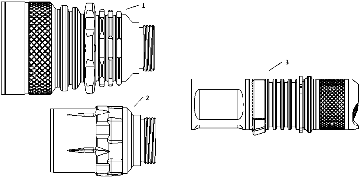
[0021] like figure 1 As shown, the operating principle of the modular lighting device shared by the tail of the present invention is: on the basis of the same tail assembly 3, a long-range head assembly 1 and a floodlight head assembly 2 are developed, and the long-range head assembly 1 and the The floodlight head assembly 2 can be screwed with the tail assembly 3 to form a lighting device, which is suitable for different lighting environments. figure 2 It is a product schematic diagram of the connection between the long-range head assembly and the tail assembly; image 3 It is a schematic diagram of the connection between the floodlight head assembly and the tail assembly. The head cover assembly adopts external thread, and the tail assembly adopts internal thread.

[0022] like Figure 4 As shown, in order to save electricity, it can i...


PUM


Abstract

The invention discloses a tail-shared modular lighting device. The tail-shared modular lighting device comprises a head assembly and a tail assembly, wherein the head assembly comprises a long shot type head assembly and a floodlight type head assembly, and both the long shot type head assembly and the floodlight type head assembly can be connected with the tail assembly to form the lighting device. The tail-shared modular lighting device solves the problem that existing users need to buy a large number of different types of lighting devices due to different use environments.

Description

technical field [0001] The invention belongs to the technical field of lighting devices, and in particular relates to a modular lighting device. Background technique [0002] There are many types of lighting devices available, and lighting devices using a single 18650 battery are the most widely used. This type of lighting device can be roughly divided into two categories: large head long-range type and middle head floodlight type. It is necessary to purchase multiple lighting devices, which brings inconvenience to users. Now the lighting devices on the market generally use a single light cup to condense the light, but when the light cup is condensed for long-distance irradiation, a large part of the light becomes more scattered, resulting in waste, thereby shortening the irradiation distance. At present, in order to pursue long-distance illumination, people will increase the lighting power, but this will undoubtedly increase the waste of electricity. Contents of the inve...

Claims


Application Information

Patent Timeline
Patent Type & Authority Applications(China)
IPC IPC(8): F21L4/00F21V5/04F21V17/12
Inventor 刘珺李鹏
Owner XENO CO SHANGLUO LTD
Learn More