Flexible strain sensor and manufacturing method thereof

A technology of strain sensor and manufacturing method, applied in the field of strain sensor, can solve the problems of poor linearity, small strain measurement range, large rock and soil deformation, etc., and achieve the effect of ensuring accuracy

Inactive Publication Date: 2019-05-07
SOUTHWEAT UNIV OF SCI & TECH
View PDF10 Cites 6 Cited by
  • Summary
  • Abstract
  • Description
  • Claims
  • Application Information

AI Technical Summary

Problems solved by technology

In comparison, the gauge coefficient of metal strain gauges is stable and linear, but the sensitivity coefficient is smaller than that of semiconductor strain gauges; the advantage of semiconductor strain gauges is high sensitivity, but it is easily affected by external factors and has poor linearity
[0005] Whether it is a metal strain gauge or a semiconductor strain gauge, their strain range is generally not greater than 200 microstrains. However, in some fields, it is often necessary to measure and monitor structures with large strains, such as in landslide tests, rock and soil The deformation of the strain gauge is very large, and ordinary resistive strain gauges cannot meet the requirements. Other strain sensors, such as Bragg optical fibers, are not suitable due to the small strain measurement range.
Although nanocomposite strain gauges can withstand large deformations and have high sensitivity, the strong nonlinearity between strain and resistance also greatly limits their applications.

Method used


Image

  • Flexible strain sensor and manufacturing method thereof
  • Flexible strain sensor and manufacturing method thereof
  • Flexible strain sensor and manufacturing method thereof

Examples


Embodiment Construction

[0028] The present invention will be further described below in conjunction with accompanying drawing:

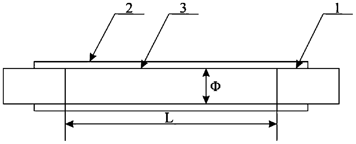
[0029] Such as figure 1 , which is a schematic diagram of the structure of the flexible strain sensor.

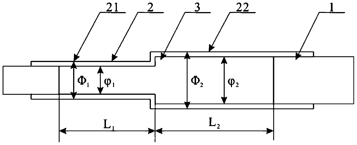
[0030] The flexible strain sensor of the present invention comprises an elastic tube 2, the elastic tube 2 is a structure with uniform inner and outer diameters, the two ends of the elastic tube 2 are respectively fixedly provided with electrodes 1, and the cross section of the electrode 1 and the cross section of the inner cavity of the elastic tube 2 The same; between the electrodes 1 is filled with a conductive solution 3 .

[0031] In an embodiment provided by the present invention, the elastic tube 2 has a constant cross-section structure, and the cross sections of the internal cavities at both ends of the elastic tube 2 are the same.

[0032] Specifically, record the resistance between the two electrodes 1 as R, and its calculation formula is:

[0033] R=ρL / S (1...


PUM


Abstract

The invention discloses a flexible strain sensor and a manufacturing method thereof. The flexible strain sensor includes an elastic tube. The elastic tube has a structure with uniform inner and outerdiameter, and electrodes are fixedly disposed at each end of the elastic tube. The cross section of the electrode is the same as the cross section of an inner cavity of the elastic tube. A conductivesolution is filled between the electrodes. The manufacturing method comprises: preparing the elastic tube having uniform inner and outer diameter, electrodes having the same cross section as that of the inner cavity at both ends of the elastic tube, the conductive solution containing the electrolyte and the like. The flexible strain sensor and the manufacturing method thereof can solve the problemthat the measuring range of the sensor in the prior art is insufficient, and has the advantages of simple structure, low cost, convenient use, strong measurement accuracy and high reliability.

Description

technical field [0001] The invention relates to a strain sensor, in particular to a flexible strain sensor and a manufacturing method thereof. Background technique [0002] Strain sensors are widely used in various engineering fields, and are the most commonly used sensing units for monitoring or measuring various structural deformations and stress conditions. At present, the most popular strain sensor is a strain gauge based on the piezoresistive effect. The piezoresistive effect means that when a conductor or semiconductor material is mechanically deformed under the action of an external force, its resistance value changes accordingly. [0003] The strain gauge is composed of a sensitive grid and other components used to measure strain. When used, it is firmly pasted on the component measuring point. The component is deformed by force, and the strain is generated at the measuring point, and the sensitive grid is deformed accordingly, causing its resistance to change. Acco...

Claims


Application Information

Patent Timeline
Patent Type & Authority Applications(China)
IPC IPC(8): G01L1/22G01B7/16
Inventor 袁有邻陆兴远徐强曹经錡苏瑞袁卫锋
Owner SOUTHWEAT UNIV OF SCI & TECH
Why Eureka
Try Eureka