Adjustment of the table position in mr imaging

a technology of mr imaging and table position, which is applied in the direction of magnetic measurement, instruments, measurement devices, etc., can solve the problems of sar being the limiting factor for a short measurement time, the patient is overloaded with radio frequency, and the measurement no longer meets the original requirements in terms of image quality and patient coverag

Inactive Publication Date: 2015-12-17
SIEMENS HEALTHCARE GMBH
View PDF15 Cites 2 Cited by
  • Summary
  • Abstract
  • Description
  • Claims
  • Application Information

AI Technical Summary

Benefits of technology

[0023]In a preferred variant, not only is a predefined range containing AdjTra measurements run through automatically, but also the determination of the table position with the smallest AdjTra value and the setting of the optimum table position are automated. In this variant the user is freed from having to make adjustments.

Problems solved by technology

The radio-frequency signals result in an overall radio-frequency load on the patient, which has to be restricted in accordance with legal requirements, because an excessive radio-frequency load could result in injury to the patient.
Thus the SAR is the limiting factor for a short measurement time in many clinical protocols.
However, the result of these techniques is that parameters of the protocol are changed such that the result of the measurement no longer satisfies the original requirements in terms of image quality and patient coverage.
Furthermore, because the measurement procedure is aborted at the start and the settings of the measurement protocol are changed, the examination sequence is interrupted and the time the patient spends in the MR scanner is increased.

Method used


Image

  • Adjustment of the table position in mr imaging
  • Adjustment of the table position in mr imaging
  • Adjustment of the table position in mr imaging

Examples


Embodiment Construction

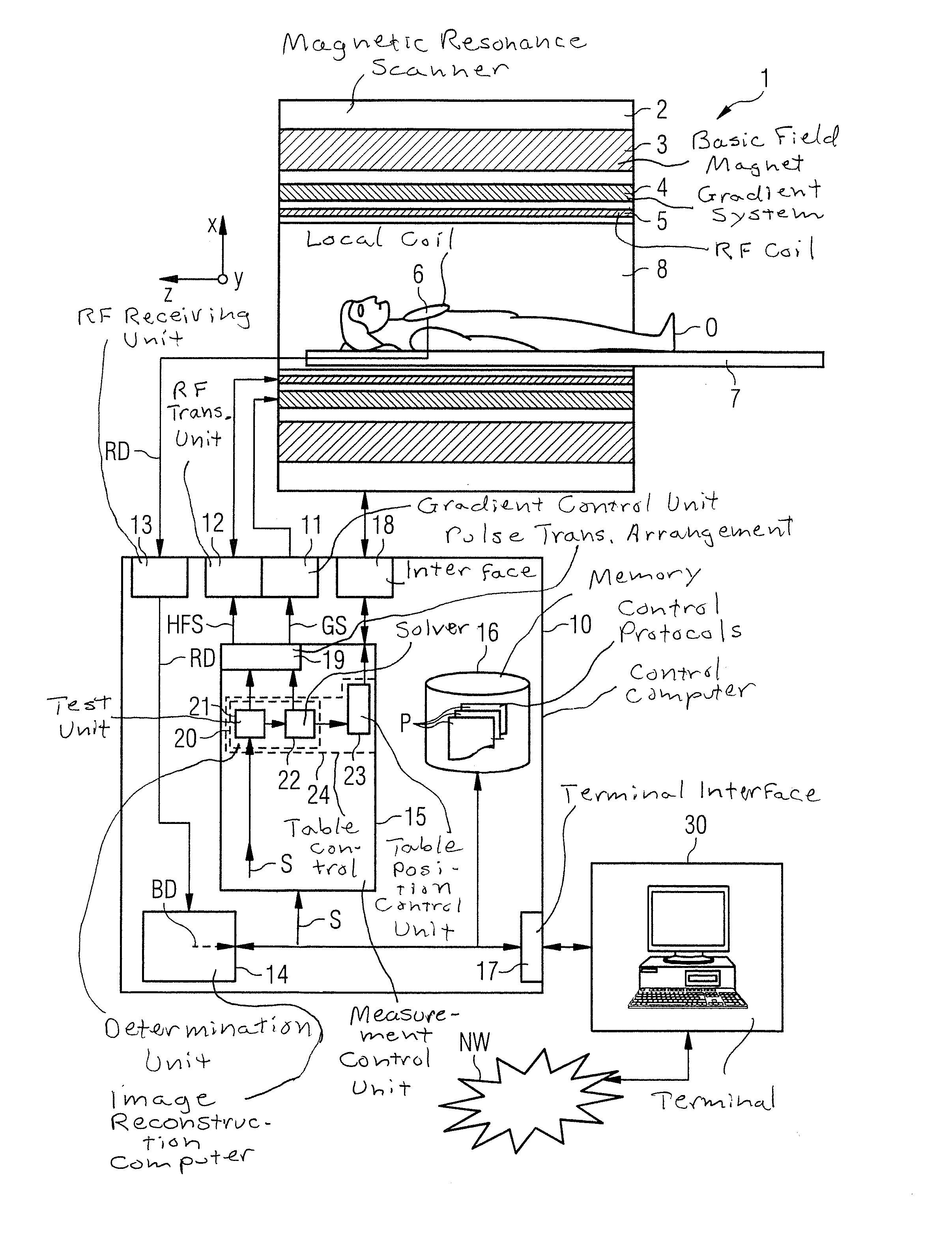
[0028]FIG. 1 is a basic schematic illustration of an inventively designed magnetic resonance system 1. It includes the actual magnetic resonance scanner 2 with an examination space 8 or patient tunnel 8 located therein. A couch or patient table 7 can be introduced into this patient tunnel 8, so that a patient O or test person lying thereon can be positioned during an examination at a particular position inside the magnetic resonance scanner 2 relative to the magnetic system and radio-frequency system arranged therein or else during a measurement can be moved between different positions.

[0029]Fundamental components of the magnetic resonance scanner 2 are a basic field magnet 3, a gradient system 4 with magnetic field gradient coils for generating magnetic field gradients in the x, y and z directions, and a whole-body radio-frequency coil 5. The magnetic field gradient coils in the x, y and z directions can be controlled independently of one another, so that by means of a predefined c...


PUM


Abstract

A method computer and magnetic resonance (MR) apparatus for controlling a table position of an examination table of the MR apparatus during an MR measurement. An SAR load is determined for an examination object with a calculated pulse sequence, at least for a first table position. Then the table position is adjusted while taking into consideration the SAR load at the first table position. The adjustment of the table position ensures that the SAR load of the examination object is reduced.

Description

BACKGROUND OF THE INVENTION[0001]1. Field of the Invention[0002]The invention concerns a method for controlling a table position of an examination table of a magnetic resonance system during a magnetic resonance measurement (data acquisition). Furthermore the invention concerns a device for controlling a table position of an examination table of a magnetic resonance system during a magnetic resonance measurement. The invention further relates to such a magnetic resonance system.[0003]2. Description of the Prior Art[0004]In a magnetic resonance system, the body to be examined is normally exposed to a relatively high basic magnetic field, for example of 3 or 7 tesla, with the use of a basic field magnet. In addition a magnetic field gradient is created with the use of a gradient system. Using a radio-frequency transmission system, radio-frequency excitation signals (RF signals) are then transmitted by suitable antennas, which results in the nuclear spins of particular atoms being reso...

Claims


Application Information

Patent Timeline
Patent Type & Authority Applications(United States)
IPC IPC(8): G01R33/30
CPCG01R33/307G01R33/583G01R33/288G01R33/4828G01R33/4835G01R33/543G01R33/5608G01R33/5611G01R33/56383
Inventor MARTIN, DIANAROLAND, JOERG
Owner SIEMENS HEALTHCARE GMBH
Why Eureka
Try Eureka