Visualization simulation experiment system and method for rock fracture response under impulsive hydrodynamic pressure

A technology of rock fissures and simulation experiments, which is applied in the direction of applying repetitive force/pulsation force to test the strength of materials, measuring devices, instruments, etc., to achieve the effect of effective recording and analysis

Pending Publication Date: 2019-05-07
HEFEI UNIV OF TECH
View PDF0 Cites 9 Cited by
  • Summary
  • Abstract
  • Description
  • Claims
  • Application Information

AI Technical Summary

Problems solved by technology

However, no researcher has used the rock model with fractures to simulate the expansion of fractures induced by fluid seepage pressure in the rock body.

Method used


Image

  • Visualization simulation experiment system and method for rock fracture response under impulsive hydrodynamic pressure
  • Visualization simulation experiment system and method for rock fracture response under impulsive hydrodynamic pressure
  • Visualization simulation experiment system and method for rock fracture response under impulsive hydrodynamic pressure

Examples


Embodiment 1

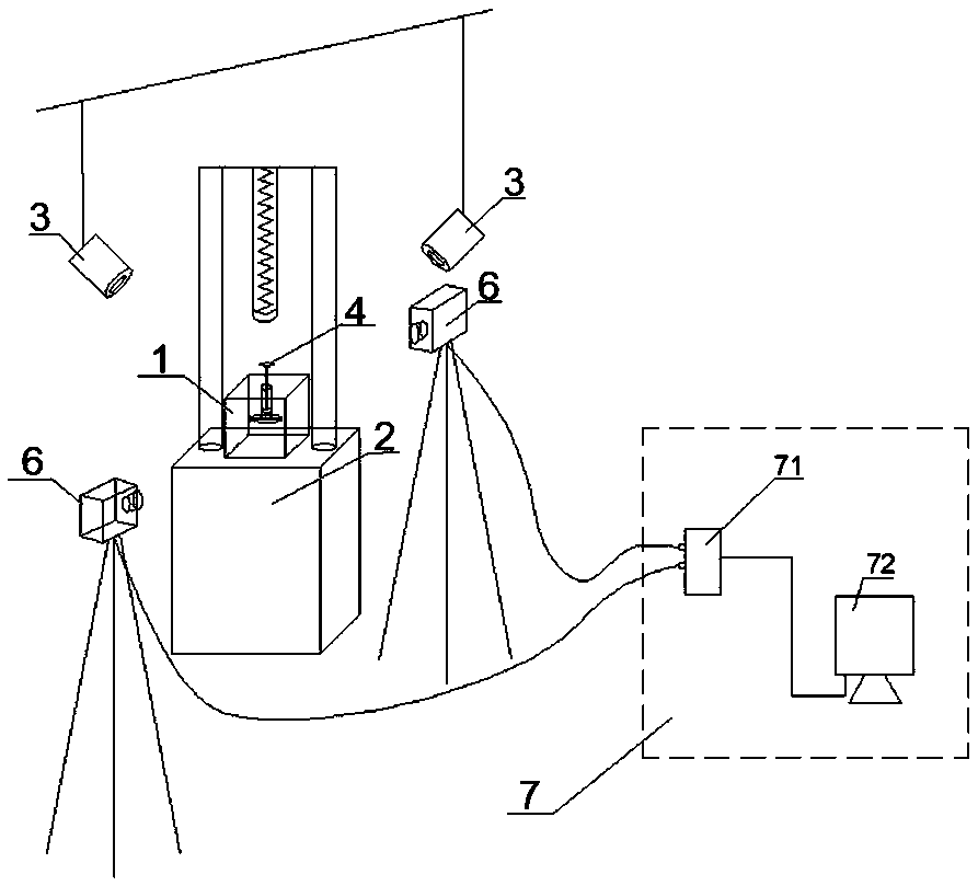
[0036] The rock fracture response visualization simulation experiment system under pulsating water pressure includes a rock model 1, a drop weight impact testing machine 2, a visualization system and an image processing device 7.

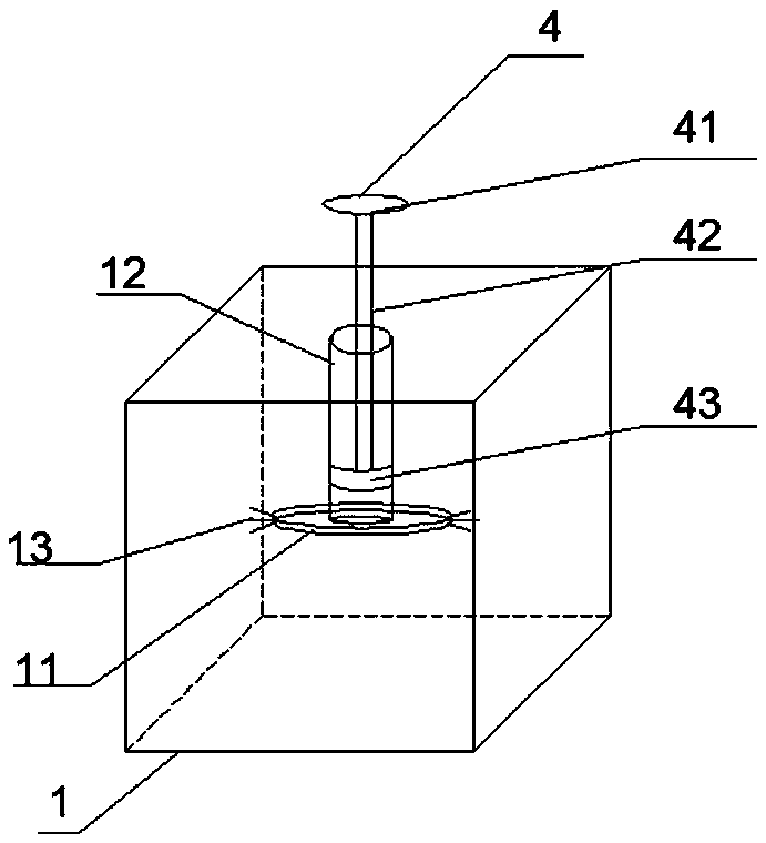
[0037] The rock model 1 is a transparent cubic rock model 1 formed by 3D printing of a transparent photosensitive resin material, with a side length of 40 cm. A cylindrical cavity 12 with an open upper end is provided in the middle of the rock model 1. The cylindrical cavity 12 The height is 20cm, and the diameter is 5cm; the central axis of the cylinder cavity 12 is coaxial with the vertical central axis of the cube; The cavity 11 is a flat cavity structure, and the two ends of the major axis of the elliptical fissure cavity 11 are all provided with a plurality of microcracks 13 inside the rock model 1; The cavities of the cavity 11 are connected.

[0038]A piston mechanism 4 is provided above the liquid level corresponding to the tracer particle ...

Embodiment 2

[0044] Embodiment 1 The experimental method of the rock fracture response visual simulation experiment system under pulsating water pressure, comprising the following steps:

[0045] (1) Put the rock model 1 in the middle of the platform of the drop hammer impact testing machine 2 and fix it.

[0046] (2) Inject the tracer particle fluid into the upper opening of the cylinder cavity 12 of the rock model 1. The tracer particle fluid fills the elliptical fracture cavity 11 and the cracks of a plurality of microcracks 13, and makes the tracer particle fluid reach the cylinder The cavity height of the body cavity 12 is 5 cm; the tracer particle fluid is a water body containing tracer particles, and has good flow field followability.

[0047] (3) Put the piston mechanism 4 into the cylinder cavity 12 of the rock model 1, press the lower end of the piston 43 into the liquid surface of the tracer particle fluid, and the upper end of the piston rod 42 protrudes from the upper end of t...


PUM


Abstract

The invention relates to the technical field of rock mass physical model tests, in particular to a visualization simulation experiment system and method for rock fracture response under impulsive hydrodynamic pressure. The system includes a rock model, a drop-weight impact testing machine, an image acquisition device and an image processing device. The rock model is a rock model of a transparent cube with fractures filled with tracer particle fluids. The drop-weight impact testing machine can simulate impulse stress applied to rock model by impact load. The image acquisition device comprises acamera mechanism and an illumination mechanism. The camera mechanism can capture the image of the rock model in the whole process, and the illumination mechanism can supplement the light of the camera mechanism. The image processing device includes an image acquisition card and a computer, the image acquisition card is connected with the camera mechanism, and the image collected by the camera mechanism is digitally processed, and the digitally processed image information is transmitted to a computer for storage and analysis, so as to realize the visual simulation of the whole process of the response of the fractured rock mass under the action of dynamic water pressure caused by blasting and other dynamic loads.

Description

technical field [0001] The invention relates to the technical field of rock mass physical model tests, in particular to a rock fissure response visualization simulation experiment system and method under pulsating water pressure. Background technique [0002] Under the action of strong dynamic stresses such as blasting and earthquakes, rock mass fissures continue to expand to form through water-conducting channels. As the fissures expand and accumulate, the permeability coefficient increases in a non-linear step, and the seepage field changes significantly, resulting in Rock mass is prone to water inrush accidents. During this period, the characteristic parameters of seepage in rock mass fractures, such as flow velocity, flow rate, and volume, are affected by space-time effects and have unsteady characteristics, so the degree and probability of damage increase significantly, which in turn aggravates the process of damage and fracture of rock mass structure, and It is diffic...

Claims


Application Information

Patent Timeline
Patent Type & Authority Applications(China)
IPC IPC(8): G01N3/02G01N3/34
Inventor 汪亦显张辉袁海平李娴张伟刘飞飞卜旭东周庭国汪志强
Owner HEFEI UNIV OF TECH
Why Eureka
Try Eureka