Orthopedic clinical traction frame

A clinical, traction frame technology, applied in non-surgical orthopedic surgery and other directions, can solve the problems of insufficient fixation, lateral displacement of the device, and high manufacturing cost, and achieves the goal of ensuring traction and treatment quality, improving use efficiency, and reducing workload. Effect

Inactive Publication Date: 2019-05-10
卢书峰
View PDF19 Cites 1 Cited by
  • Summary
  • Abstract
  • Description
  • Claims
  • Application Information

AI Technical Summary

Problems solved by technology

[0002] In the surgical treatment and later rehabilitation treatment of orthopedic patients, it is necessary to provide external traction assistance to the affected part of the patient to ensure better and more efficient treatment by the medical staff or faster and more reasonable recovery of the affected part. Traction therapy is the application of external force to the body. It is a method to apply a traction force to a certain part or joint to make it separate to a certain extent, and the surrounding soft tissue is properly stretched, so as to achieve the purpose of treatment. However, the traditional traction device has many problems, complex structure, and high production cost. Large, low popularity, inconvenient installation and use, not firm enough to fix, prone to sideways movement of the device, causing secondary trauma to the affected part of the patient, which brings great trouble to the use of medical staff, and can not realize the traction part according to the demand The rapid stretching and traction of the traction part cannot realize the rapid clamping and fixing of the traction column at the traction part, and the traction force and traction time cannot be reasonably controlled, so that it is impossible to realize the appropriate timing traction auxiliary treatment for the patient's traction part, which virtually increases the number of medical staff. The workload, the quality of traction and treatment is difficult to be guaranteed, resulting in low efficiency of the use of the traction frame, so the realization of a clinical orthopedic traction frame that can solve such problems is imperative

Method used


Image

  • Orthopedic clinical traction frame
  • Orthopedic clinical traction frame

Examples


Embodiment Construction

[0013] The following will clearly and completely describe the technical solutions in the embodiments of the present invention with reference to the accompanying drawings in the embodiments of the present invention. Obviously, the described embodiments are only some, not all, embodiments of the present invention. Based on the embodiments of the present invention, all other embodiments obtained by persons of ordinary skill in the art without making creative efforts belong to the protection scope of the present invention.

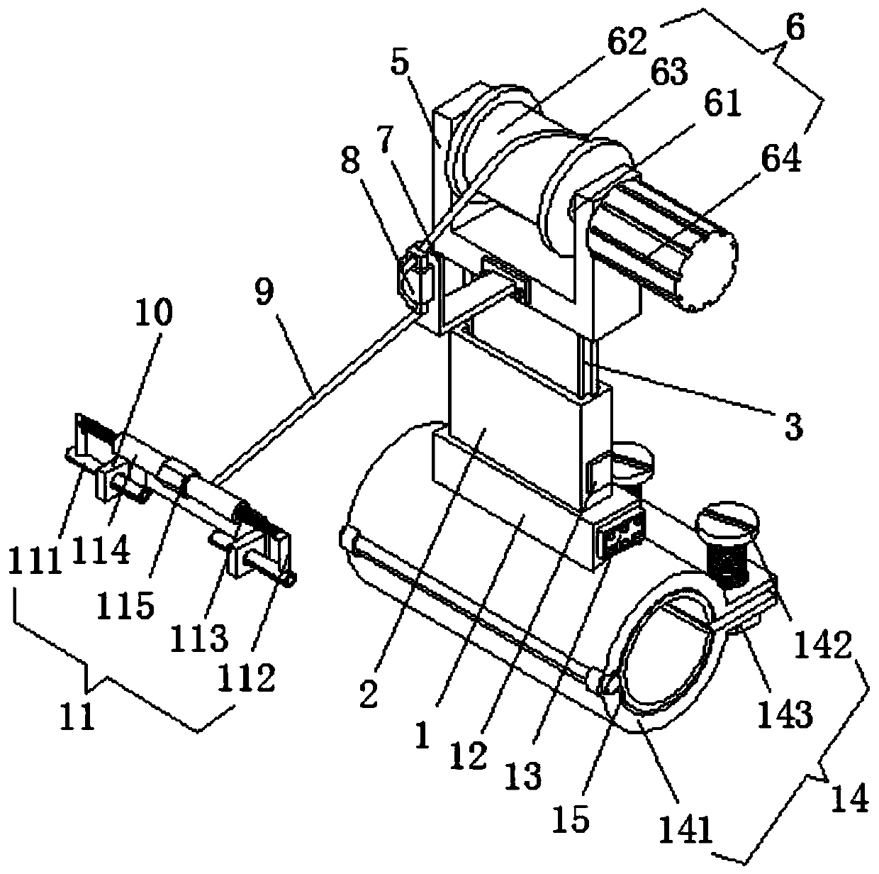
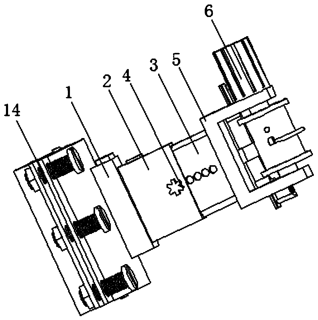
[0014] see Figure 1-2 , the present invention provides a technical solution: a traction frame for orthopedic clinical use, including a base plate 1, a groove plate 2 is provided on the upper end of the base plate 1, and the chute on both sides of the groove of the groove plate 2 and the two sides of the telescopic plate 3 The slide bar is slidingly connected, and the rear side threaded hole of the groove plate 2 is provided with an adjusting bolt 4, and the b...


PUM


Abstract

The invention discloses an orthopedic clinical traction frame. The traction frame comprises a bottom plate, a groove plate is arranged at the upper end of the bottom plate, sliding grooves on the twosides of a groove of the groove plate are slidably connected with sliding strips on the two sides of a telescopic plate, adjusting bolts are arranged in rear side threaded holes on the rear side of the groove plate, and the bottoms of the adjusting bolts are in threaded connection with the threaded holes which are uniformly distributed on the rear side of the telescopic plate. The orthopedic clinical traction frame has the advantages that the structure is simple, the production cost is lower, the installing and using are convenient, great convenience is brought for the use of medical workers,the rapid stretching traction on a traction part can be achieved through a traction device, rapid clamping fixing on a traction column of the traction part is achieved through a clamping fixing device, proper regular traction auxiliary treatment on the traction part of a patient is achieved under the real-time pulling force monitoring of a pulling force sensor and the traction timing of a timer, the working intensity of the medical workers is relieved, the traction and treatment quality is ensured, and the using efficiency of the traction frame is improved.

Description

technical field [0001] The invention relates to the technical field of medical auxiliary equipment, in particular to a clinical traction frame for orthopedics. Background technique [0002] In the surgical treatment and later rehabilitation treatment of orthopedic patients, it is necessary to provide external traction assistance to the affected part of the patient to ensure better and more efficient treatment by the medical staff or faster and more reasonable recovery of the affected part. Traction therapy is the application of external force to the body. It is a method to apply a traction force to a certain part or joint to make it separate to a certain extent, and the surrounding soft tissue is properly stretched, so as to achieve the purpose of treatment. However, the traditional traction device has many problems, complex structure, and high production cost. Large, low popularity, inconvenient installation and use, not firm enough to fix, prone to sideways movement of the...

Claims


Application Information

Patent Timeline
Patent Type & Authority Applications(China)
IPC IPC(8): A61F5/045
Inventor 卢书峰邹姗
Owner 卢书峰
Why Eureka
Try Eureka