Material distribution device and method

A material distribution and feeding device technology, applied in chemical instruments and methods, mixers with rotary stirring devices, transportation and packaging, etc., can solve the problems of easy stratification, dead ends, and high equipment investment costs, and achieve continuous distribution and mixing , the effect of stable work and simple structure

Pending Publication Date: 2019-05-10
KINGFA SCI & TECH CO LTD
View PDF0 Cites 2 Cited by
  • Summary
  • Abstract
  • Description
  • Claims
  • Application Information

AI Technical Summary

Problems solved by technology

The working method is mostly intermittent batch mixing. Usually, a certain amount of multi-component materials to be mixed is placed in the mixing equipment, and the blades are stirred at a certain speed for a period of time, and then the mixed materials are discharged. Due to the particles and powder in the mixture The particle size, density, and fluidity of materials such as granules vary greatly, so it is difficult to achieve a uniform mixing effect, and it is easy to separate after mixing, during discharge, transportation, and use, which affects the stability of the product.
[0004] On the other hand, when these intermittent batch stirring devices are used, they are generally filled with materials with an effective volume of 40% to 60%. High-speed stirring is likely to cause temperature rise and damage the materials. During the mixing process, accumulation and agglomeration are pron

Method used


Image

  • Material distribution device and method
  • Material distribution device and method
  • Material distribution device and method

Examples


Embodiment

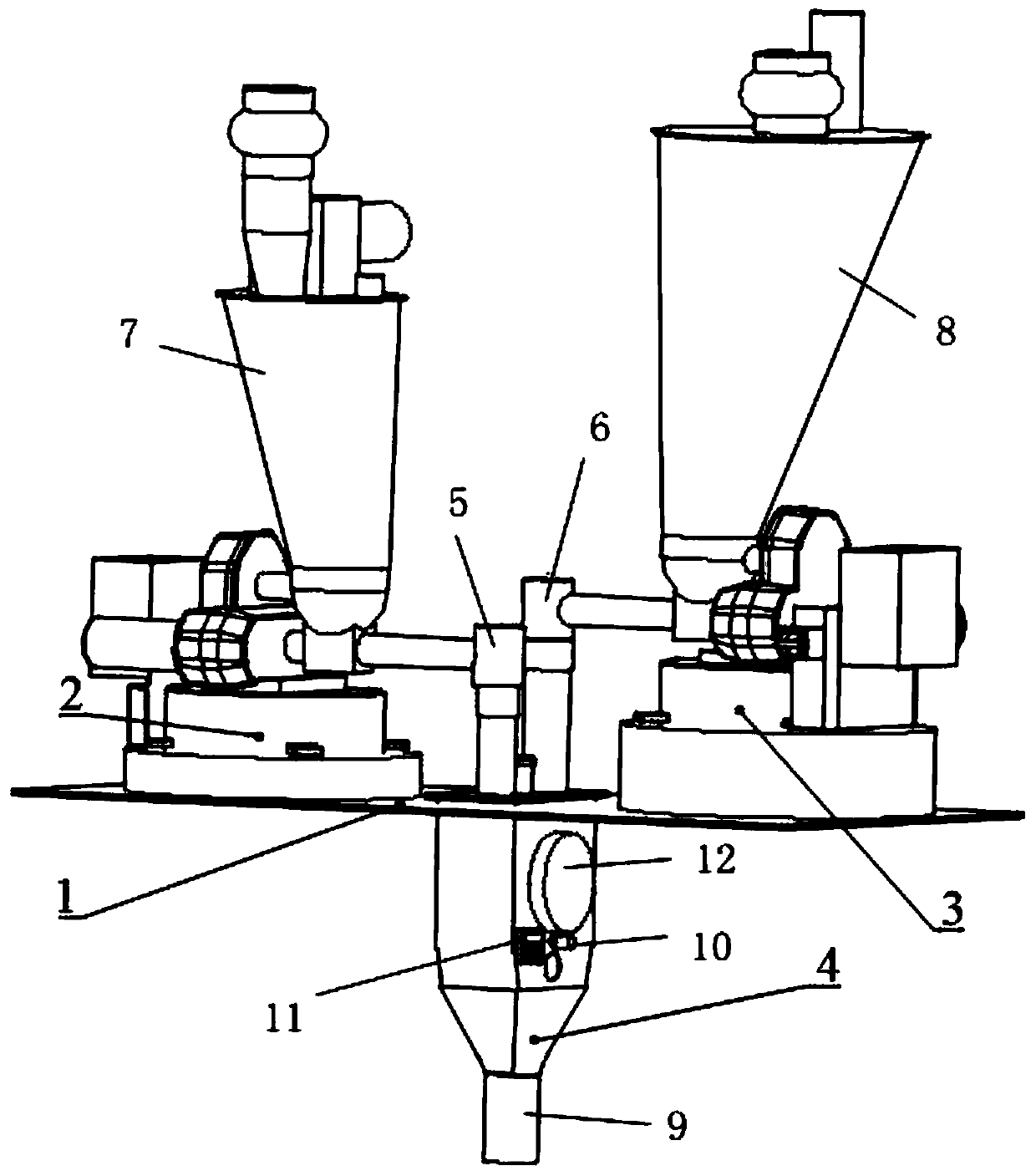
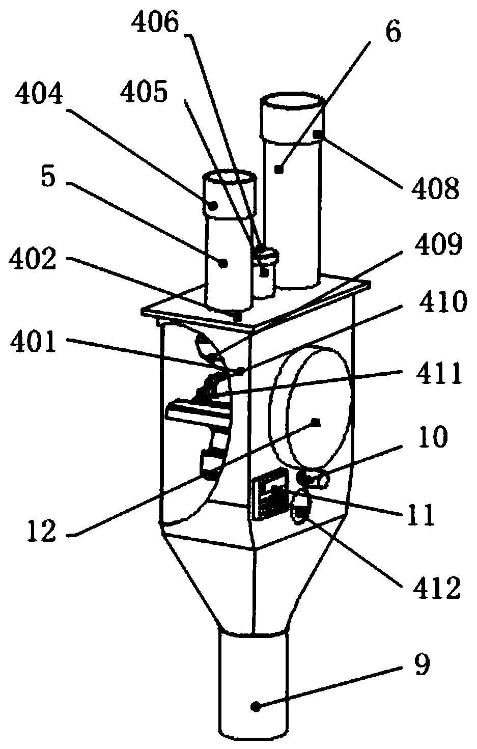
[0051] Such as figure 1 As shown, this embodiment provides a material distribution device, including a distributor body 4, a first feeding device and a second feeding device.

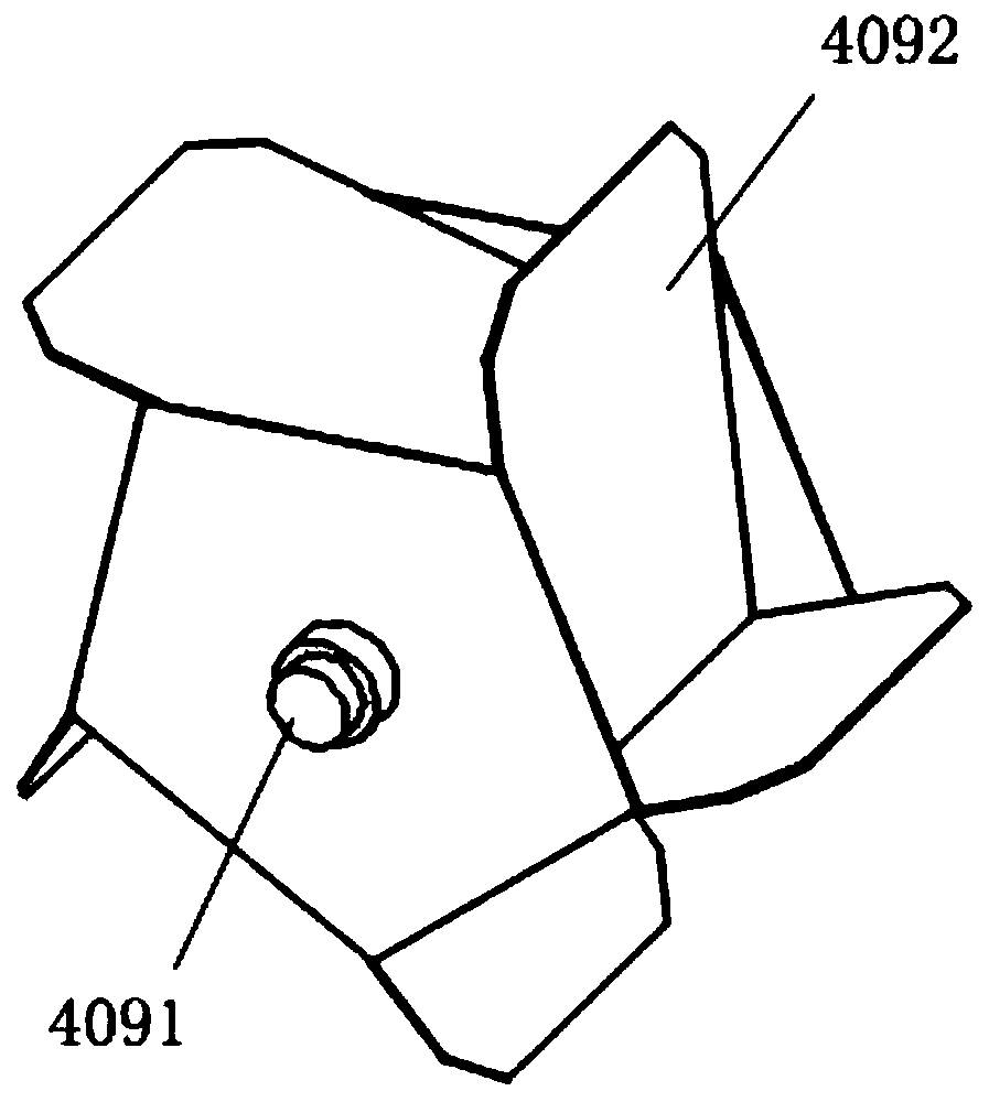
[0052] In this embodiment, the distributor body 4 includes a cylinder 401, the upper part of the cylinder 401 is provided with a first feed channel and a second feed channel, the inside of the cylinder 401 is provided with a rotating paddle 409, and the bottom of the cylinder 401 A discharge port 9 is provided. Specifically, the rotating paddle 409 includes a rotating shaft 4091 and blades 4092 , and the blades 4092 are fixed on the rotating shaft 4091 . Preferably, the number of blades 4092 is not less than 3, and the number of blades 4092 is preferably 5, 6, or 7. A supporting structure is provided inside the cylinder 401, and a "U"-shaped or semicircular mounting groove is opened on the supporting structure, and the rotating shaft 4091 of the rotating paddle 409 is installed in the mounting groove....


PUM


Abstract

The invention provides a material distribution device and a method. In the material distribution device, a distributor main body comprises a barrel; a rotating paddle is arranged in the barrel; a discharging port is formed on the bottom of the barrel; a first feeding device is arranged for conveying a first material into the barrel from a first feeding channel; a second feeding device is arrangedfor conveying a second material into the barrel from a second feeding channel; a torque difference exists between the torque of the first material acting on the rotating paddle and the torque of the second material acting on the rotating paddle; the rotating paddle can rotate under the effect of the torque difference. A driving mechanical stirring device is avoided; structure is simpler and working is more stable and efficient; the material distribution device is suitable for various materials, is capable of realizing continuous distribution and mixing of materials and does not result in interior overheating; when rotating speed is lower, a driving device can be utilized to supply power for assisting the rotating paddle in rotating; when material flow is smaller, the material still can beuniformly mixed; the material distribution device can be used for micro-layer distribution and mixing of materials at any material flow ratio.

Description

technical field [0001] The invention relates to the technical field of batching, in particular, to a material distribution device and method. Background technique [0002] Material mixing is an indispensable link in the production and manufacturing of many industries, such as modified plastics industry, food processing industry and chemical products. The uniformity of material mixing directly determines the quality and stability of the product, and the production raw materials often have multiple components with different proportions, shapes and particle sizes, and it is difficult to mix them uniformly during mixing. If it is stirred and mixed manually, the workload is very large, the labor intensity of the operator is high, and the effect of material mixing is not ideal. [0003] At present, the mixing equipment is mainly based on various mixing forms. Commonly used are: high-speed mixer, low-speed mixer, horizontal mixer, double-helix conical mixer, gravity-free mixer and...

Claims


Application Information

Patent Timeline
IPC IPC(8): B01F7/02B01F7/04B01F15/00
CPCB01F27/60B01F27/70B01F35/00
Inventor 李东马鹏涛廖洋威王业停余兴兴曹奇
Owner KINGFA SCI & TECH CO LTD
Why Eureka
Try Eureka