Body wash production stirring system
A mixing system and shower gel technology, which is applied to mixer accessories, dissolving, mixers, etc., can solve the problems of general effect, single stirring method, and inability to add shower gel raw materials intermittently, so as to improve mixing efficiency and mixing effect Effect
- Summary
- Abstract
- Description
- Claims
- Application Information
AI Technical Summary
Problems solved by technology
Method used
Image

Examples
specific Embodiment approach 1
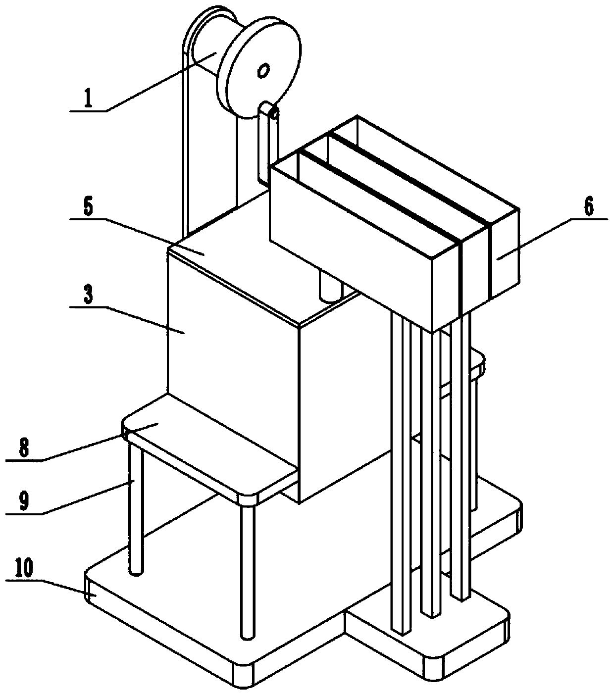
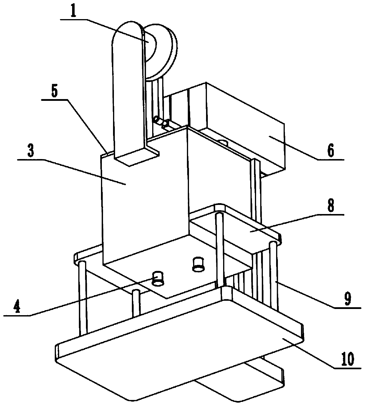
[0027] Such as Figure 1-11 As shown, a mixing system for shower gel production includes a stirring drive mechanism 1, a stirring mechanism 2, a stirring box 3, a liquid outlet pipe 4 with a control valve, a detachable box cover 5, a material storage mechanism 6, and a feeding control mechanism 7. The upper seat plate 8, the support rod 9 and the lower seat plate 10, the top surface of the stirring box 3 is hollowed out, and the top of the stirring box 3 is sealed and fixedly connected to the removable box cover 5; the bottom end of the stirring box 3 is fixedly connected and Connected to the liquid outlet pipe 4; the left and right ends of the mixing box 3 are respectively fixedly connected to an upper seat plate 8; the bottom end of the upper seat plate 8 is fixedly connected to the lower seat plate 10 through two support rods 9; the stirring drive mechanism 1 is fixedly connected to the rear side of the stirring box 3; the stirring drive mechanism 1 is connected to the stir...
specific Embodiment approach 2
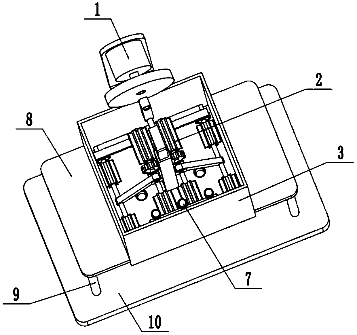
[0029] Such as Figure 1-11As shown, the stirring drive mechanism 1 includes a servo motor 1-1, a motor base 1-2, a rotating disk 1-3, an eccentric shaft 1-4, an eccentric connecting rod 1-5, a push-pull shaft 1-6 and a push-pull block 1 -7; the servo motor 1-1 is fixedly connected to the rear side of the mixing box 3 through the motor base 1-2; the front end of the output shaft of the servo motor 1-1 is fixedly connected to the rotating disk 1-3; the rotating The eccentric position of the disk 1-3 is fixedly connected to the eccentric shaft 1-4; one end of the eccentric connecting rod 1-5 is connected to the eccentric shaft 1-4 in rotation, and the other end of the eccentric connecting rod 1-5 is connected to the push-pull On the shaft 1-6, the front end of the push-pull shaft 1-6 is fixedly connected to the push-pull block 1-7; the push-pull block 1-7 is fixedly connected to the stirring mechanism 2. When the stirring drive mechanism 1 is in use, the servo motor 1-1 adopts ...
specific Embodiment approach 3
[0030] Such as Figure 1-11 As shown, the stirring mechanism 2 includes a rectangular sliding rod 2-1, a rectangular sleeve 2-2, a double-sided rack 2-3, a lifting slide 2-4, a lifting shaft 2-5, a lifting gear 2-6, Lifting stirring wheel 2-7, side connecting rod 2-8, movable shaft 2-9, movable gear 2-10, fixed rack 2-11, L-shaped fixed block 2-12, trough frame 2-13 and movable stirring Wheel 2-14; the top of the rectangular slide bar 2-1 is fixedly connected to the push-pull block 1-7, and the middle end of the rectangular slide bar 2-1 is sealed and slidably connected to the rectangular through hole at the middle end of the detachable box cover 5; The sliding fit of the rectangular slide bar 2-1 is connected to the inside of the rectangular casing 2-2, and the bottom end of the rectangular casing 2-2 is fixedly connected to the inner bottom surface of the mixing box 3; the rectangular casing 2-2 The rear side is fixedly connected with the double-sided rack 2-3, the left and...
PUM
 Abstract
Description
Claims
Application Information
 - R&D
- Intellectual Property
- Life Sciences
- Materials
- Tech Scout
- Unparalleled Data Quality
- Higher Quality Content
- 60% Fewer Hallucinations
Browse by: Latest US Patents, China's latest patents, Technical Efficacy Thesaurus, Application Domain, Technology Topic, Popular Technical Reports.
© 2025 PatSnap. All rights reserved.Legal|Privacy policy|Modern Slavery Act Transparency Statement|Sitemap|About US| Contact US: help@patsnap.com