A tank cleaning system and cleaning method

A cleaning system and tank technology, applied in cleaning methods and appliances, chemical instruments and methods, cleaning hollow objects, etc., can solve problems affecting the use of tanks, limited space on drilling platforms, small volume, etc., and achieve the goal of improving operating efficiency Effect

Active Publication Date: 2020-11-03
CHINA NAT OFFSHORE OIL CORP +1
View PDF3 Cites 0 Cited by
  • Summary
  • Abstract
  • Description
  • Claims
  • Application Information

AI Technical Summary

Problems solved by technology

[0002] Mud is the "blood" of drilling engineering. During long-term use, mud will settle in the mud tank, which will affect the effective volume of the mud tank. If it is not cleaned in time, it will affect the use of the tank, and cross-contamination of mud may also occur etc., so the tank needs to be cleaned regularly
[0003] Due to the small size of the mud tank on the drilling platform and the limited space on the drilling platform, it is difficult for general cleaning equipment to carry out cleaning operations. At present, the conventional cleaning is mostly carried out manually into the tank body, and manual cleaning is still the main method. Serious potential safety and environmental hazards: 1. The manual cleaning method often uses personnel to enter the tank for cleaning. The operating space in the tank is narrow, it is in a semi-closed state, and the oxygen content is low. For a long time, there have been safety accidents caused by personnel entering the tank for cleaning occur, seriously affecting the safety of mud services
2. The manual cleaning method often piles up the sludge in the open air, which will cause soil and water pollution, and environmental disputes caused by it happen from time to time

Method used


Image

  • A tank cleaning system and cleaning method

Examples


Embodiment approach

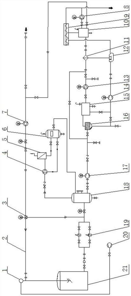
[0021] In actual operation, the cleaning liquid may be oil-based or water-based. When water-based cleaning liquid is used, the oily substance contained in the water-based cleaning waste liquid needs to be removed during the recycling process. As an embodiment, the tank cleaning system further includes an oil-water separation device, the first liquid storage tank 10 is provided with a first liquid storage area and a second liquid storage area, and the first solid-liquid separation device 11 The drain port of the first liquid storage area is connected to the first liquid storage area and the second liquid storage area through the first pipeline and the second pipeline respectively, and the liquid discharge port of the first liquid storage area is connected to the cleaning liquid delivery pipe Road 2, the cleaning waste liquid in the second liquid storage area is returned to the first liquid storage area after oil-water separation by the oil-water separation device. In this embod...


PUM


Abstract

The invention relates to a tank cleaning system and a cleaning method, and relates to the technical field of tank cleaning devices and methods. The tank cleaning system comprises a to-be-cleaned tank,a filtering device, a buffer tank, a first solid-liquid separating device and a first liquid storage tank which are arranged in sequence, the filtering device is used for filtering cleaning waste liquid discharged from the to-be-cleaned tank, the buffer tank is used for storing cleaning waste liquid filtered by the filtering device, the first solid-liquid separating device is used for conductingsolid-liquid separation on cleaning waste liquid discharged from the buffer tank, the first liquid storage tank is used for collecting the cleaning waste liquid discharged from the first solid-liquidseparating device and obtained after the solid-liquid separation, a liquid outlet of the first liquid storage tank is connected to a cleaning liquid delivery pipe, and the cleaning liquid delivery pipe is used for conveying cleaning liquid into the to-be-cleaned tank. According to the tank cleaning system in the embodiment, the cleaning waste liquid obtained after cleaning can be recycled, the cleaning liquid can be saved, and environmental pollution can be avoided; and automatic control is conveniently achieved, and the cleaning operation efficiency is improved.

Description

technical field [0001] The present application relates to the technical field of tank cleaning devices and methods, in particular to a tank cleaning system and cleaning method. Background technique [0002] Mud is the "blood" of drilling engineering. During long-term use, mud will settle in the mud tank, which will affect the effective volume of the mud tank. If it is not cleaned in time, it will affect the use of the tank, and cross-contamination of mud may occur etc. Therefore, the tank needs to be cleaned regularly. [0003] Due to the small size of the mud tank on the drilling platform and the limited space on the drilling platform, it is difficult for general cleaning equipment to carry out cleaning operations. At present, the conventional cleaning is mostly carried out manually into the tank body, and manual cleaning is still the main method. Serious safety and environmental hazards: 1. The manual cleaning method often uses personnel to enter the tank for cleaning. Th...

Claims


Application Information

Patent Timeline
Patent Type & Authority Patents(China)
IPC IPC(8): B08B9/08B08B9/093
Inventor 张贵磊侯林祝国伟周波李成胜王伟于海安李斌张冉刘洪李
Owner CHINA NAT OFFSHORE OIL CORP
Why Eureka
Try Eureka