Novel stamping mold

A stamping die, a new type of technology, applied in the field of stamping die, can solve the problems of unsmooth feeding, reduced production efficiency, material jamming, etc., and achieve the effect of avoiding material jamming and not easy to deform

Inactive Publication Date: 2019-05-10
SUZHOU BAIDA PRECISION MACHINERY
View PDF13 Cites 0 Cited by
  • Summary
  • Abstract
  • Description
  • Claims
  • Application Information

AI Technical Summary

Problems solved by technology

[0002] The lifting device installed on the lower die in the existing stamping die adopts the lifting device of the dome material pin to lift the material, because the surface contacting the product has only one round surface, and because the ejector pin is connected

Method used


Image

  • Novel stamping mold

Examples


Example Embodiment

[0011] The present invention will be further described below in conjunction with the drawings.

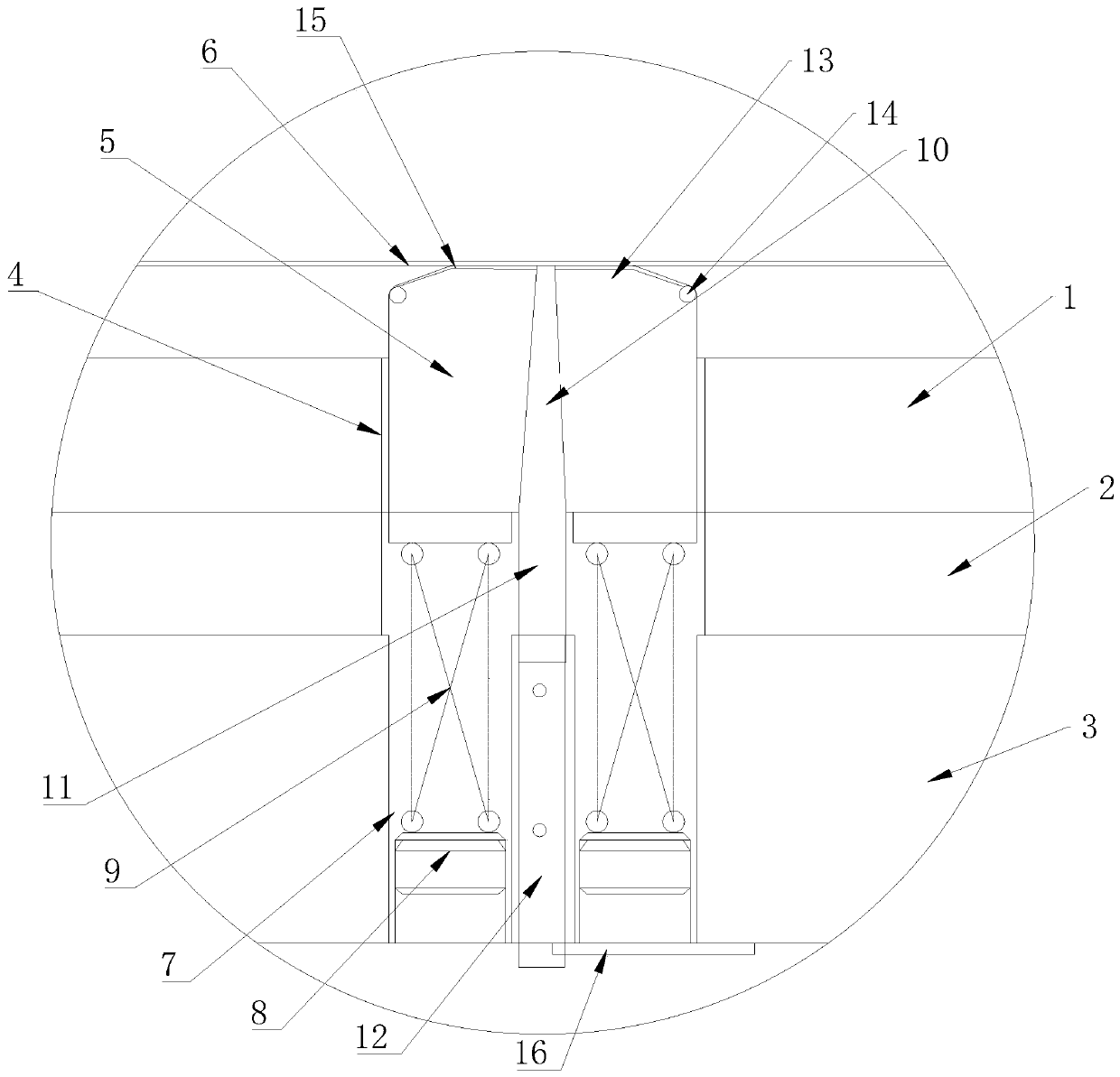
[0012] Such as figure 1 As shown, a new type of stamping die includes a lower die assembly. The lower die assembly includes a lower template 1, a lower backing plate 2, and a lower die seat 3, which are sequentially arranged from top to bottom. The backing plate 2 is respectively provided with a through groove 4, a top block 5 is arranged in the through groove 4, a fixing groove 7 is arranged in the lower mold base 3, and two fixing screws 8 are arranged at the bottom of the fixing groove 7 , A spring 9 is connected between the top block 5 and the two fixing screws 8, a slope 13 is provided on the top of the top block 5, a needle roller 14 is provided on the bottom of the slope 13, and the slope 13 is provided with Tungsten steel layer 15, the middle of the top block 5 is provided with a slag discharge hole 10, the bottom of the top block 5 is provided with a slag discharge pipe 11 c...


PUM


Abstract

The invention discloses a novel stamping mold. According to the technical scheme, the novel stamping mold comprises a lower mold assembly, the lower mold assembly comprises a lower mold plate, a lowerbase plate and a lower mold base which are sequentially arranged from top to bottom, the lower mold plate and the lower base plate are each provided with a through groove in a penetrating manner, ejecting blocks are arranged in the through grooves, a fixed groove is formed in the lower mold base, two fixed screws are arranged on the bottom of the fixed groove, springs are connected between the ejecting blocks and the fixed screws, slopes are arranged on the tops of the ejecting blocks, roller pins are arranged on the bottoms of the slopes, tungsten steel layers are arranged on the slopes, slag discharge holes are formed in the middles of the ejecting blocks in a penetrating manner, the bottoms of the ejecting blocks are provided with slag discharge pipes communicating with the slag discharge holes, guide holes allowing the slag discharge pipes to extend in are formed in the lower mold base, and inflation pipes extending into the guide holes are arranged in the lower mold base. Feedingis smooth and free of clamping, the service life is long, and continuous production can be achieved.

Description

technical field [0001] The invention relates to the technical field of stamping dies, in particular to a novel stamping die. Background technique [0002] The lifting device installed on the lower die in the existing stamping die adopts the lifting device of the dome material pin to lift the material, because the surface contacting the product has only one round surface, and because the ejector pin is connected to the spring, the top of the ejector pin will move Protruding from the upper template, which will lead to unsmooth feeding and material jamming, which will fail to meet the requirements of continuous production and reduce production efficiency. Therefore, how to design a kind of buoyancy structure that can feed materials smoothly and realize continuous production is just the problem to be solved by the inventors. Contents of the invention [0003] Aiming at the deficiencies in the prior art, the main purpose of the present invention is to provide a floating struct...

Claims


Application Information

Patent Timeline
IPC IPC(8): B21D37/10B21D37/12
Inventor 丁飞
Owner SUZHOU BAIDA PRECISION MACHINERY
Why Eureka
Try Eureka