Linkage displacement bidirectional rebar hoop bending machine

A two-way steel bar and hoop bending machine technology, which is applied in the field of construction equipment, can solve problems such as positioning structure coordination and complex hydraulic control systems, and achieve the effects of continuous operation, high degree of automation, and simplified hydraulic control circuits

Pending Publication Date: 2019-05-10
冯广建
View PDF12 Cites 0 Cited by
  • Summary
  • Abstract
  • Description
  • Claims
  • Application Information

AI Technical Summary

Problems solved by technology

[0004] The above conjoined two-way hydraulic steel bar bending machine needs to be equipped with two bending mechanisms, which are driven by two power devices respectively, which makes the hydraulic control system more complicated.
In order to simplify the equipment, the applicant specially developed a two-way steel bar bending machine equipped with a two-way bending mechanism to reduce the number of bending mechanisms, but it still needs to solve the problem of positioning when the steel bars are bent forwardly and reversely. problems with structure

Method used


Image

  • Linkage displacement bidirectional rebar hoop bending machine
  • Linkage displacement bidirectional rebar hoop bending machine
  • Linkage displacement bidirectional rebar hoop bending machine

Examples


Embodiment 1

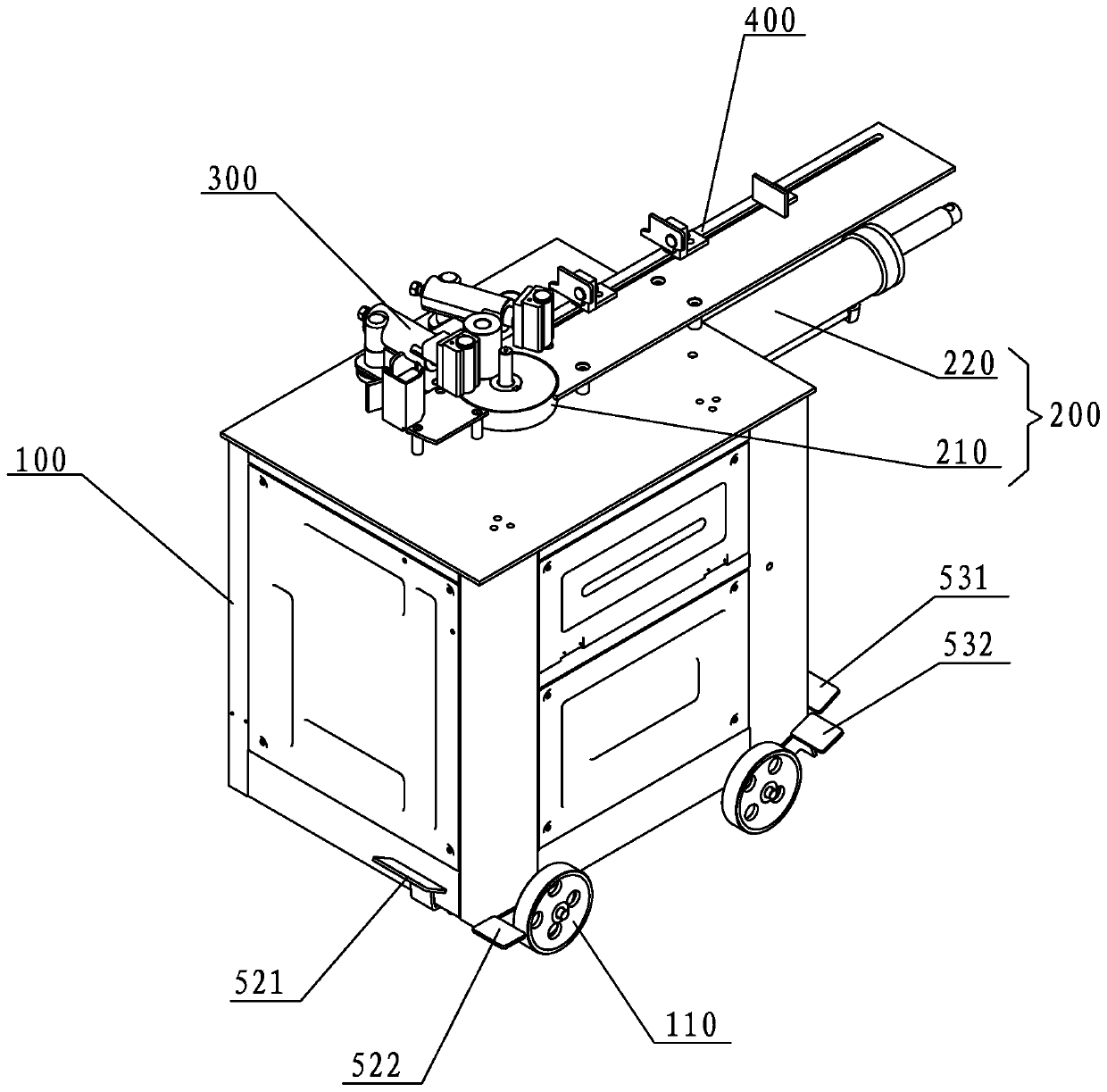
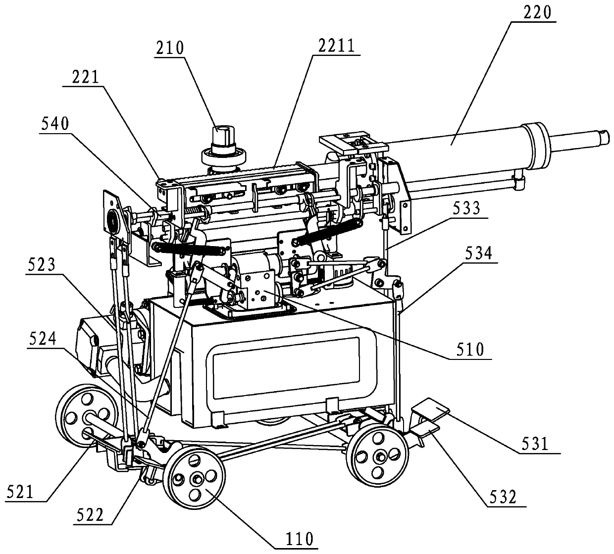
[0047] refer to Figure 1 to Figure 11 , a preferred embodiment provided by the present invention, linkage displacement two-way steel bar hoop bending machine, includes a frame 100, the frame 100 is provided with an oil tank, a two-way bending mechanism 200, and the two-way bending mechanism 200 includes a bending The turntable 210 and the power member 220, the power member 220 is preferably a hydraulic cylinder with a forward stroke and a reverse stroke. The bending turntable 210 is rotatably arranged on the frame 100, and the bending turntable 210 is provided with a center pin and a bending pin, and the bending pin rotates around the center pin. Preferably, the center pin can The telescoping is set on the bending turntable 210 . A drive gear is also arranged below the bending turntable 210 . The piston rod of the power part 220 is connected with a travel bracket 221, and the travel bracket 221 is provided with a drive rack 2211 that engages with the drive gear and drives t...

Embodiment 2

[0056] refer to Figure 12 , Figure 13 , the present invention also provides a second implementation of the linkage displacement pin plate 300 . In the first embodiment, the linked displacement pin plate 300 is displaced through rotation, so as to approach or move away from the bending turntable 210 . In this embodiment, the frame 100 is provided with a bar-shaped guide groove 350, and the forward pin stop plate 310 and the reverse pin stop plate 320 are installed on the guide slot 350 and can translate along the guide slot 350. . Such as Figure 12 As shown, when the steel bar is bent in the forward direction, the forward stopper plate 310 moves close to the bending turntable 210, and the reverse stopper plate 320 moves away from the bending turntable 210; otherwise, the forward stopper plate 310 moves away from the bending turntable 210, reverse The stop pin plate 320 is close to the bending turntable 210, such as Figure 13 shown. Preferably, the forward pin stop pla...

Embodiment 3

[0058] The present invention also provides a third embodiment of the linkage displacement stop plate. The forward pin stop plate and the reverse pin pin plate can also be arranged on the frame in a lifting manner. When the bending turntable bends the steel bar forward, the forward pin stop plate rises to match the center pin shaft and the bending pin shaft pair. When the steel bar is positioned, the reverse baffle plate descends, and when the bending turntable reversely bends the steel bar, the reverse baffle plate rises to coordinate with the central pin shaft and the bending pin shaft to position the reinforcement, and the forward baffle plate descends. Except that the movement mode of the linkage displacement baffle plate is different, other mechanisms of the linkage displacement two-way steel bar bending machine provided by this embodiment are the same as those of the first embodiment.


PUM


Abstract

The invention discloses a linkage displacement bidirectional rebar hoop bending machine. The linkage displacement bidirectional rebar hoop bending machine comprises a machine frame, and a bidirectional bending mechanism, a linkage displacement stop pin plate, a shaft-coupling type angle conversion control mechanism and a sizing mechanism which are arranged on the machine frame, wherein the bidirectional bending mechanism is capable of bending a rebar in a two-way mode, the linkage displacement stop pin plate is used for providing positioning for bending the rebar to ensure the quality of the rebar, the shaft-coupling type angle conversion control mechanism is used for controlling the bending angle of the rebar, and the sizing mechanism can be used for realizing the fixed length bending ofthe rebar. The linkage displacement bidirectional rebar hoop bending machine provided by the invention has the following advantages that rebar hoop bending can be realized by one machine, the operation is simple and continuous, the efficiency is high, a hydraulic control loop is simplified, equipment structure is simplified, equipment function is perfected, fixed-length bending is carried out, sothat product standardization is realized, the control is simple and easy, and the automation degree is high.

Description

technical field [0001] The invention relates to the field of construction equipment, in particular to a linkage displacement bidirectional steel bar hoop bending machine. Background technique [0002] The steel bar bending machine is used to bend steel bars, which are widely used in the construction industry to make steel hoops for construction. The steel bar bending forming machine uses a bending mechanism composed of a turntable, a central pin and a rotating pin to bend steel bars. The turntable is driven by a power device to rotate, and the rotating pin is fixed on the turntable to rotate with the turntable. The turntable and rotating pin Rotate around the center pin, and use the torque generated by the rotation of the rotating pin to bend the steel bars placed between the rotating pin and the center pin. [0003] The existing steel bar bending forming machine generally only has one bending mechanism, which can bend the steel bar at one or two angles. When bending the st...

Claims


Application Information

Patent Timeline
Patent Type & Authority Applications(China)
IPC IPC(8): B21F1/00
Inventor 冯广建
Owner 冯广建
Why Eureka
Try Eureka