
Stud welding laser locating system and working method thereof

A working method and stud welding technology, which is applied in the direction of manufacturing tools, welding equipment, welding accessories, etc., can solve problems such as shape, size deformation, welding position error, and tolerance inconsistency, so as to save installation time, improve product quality, and install flexible effects

Inactive Publication Date: 2019-05-10
珠海市福尼斯焊接技术有限公司
View PDF6 Cites 3 Cited by
  • Summary
  • Abstract
  • Description
  • Claims
  • Application Information

AI Technical Summary

Problems solved by technology

Generally, the parts that need to be welded are fused by heating. Due to the heating, the temperature field of the heated part is inconsistent with other unheated parts, which easily leads to deformation of shape and size; in addition, due to the installation accuracy of the workpiece and the size of the workpiece The influence of tolerances will cause tolerances in the processed workpieces, and the tolerances of each workpiece are inconsistent, which leads to large errors in the welding position when stud welding is performed on the relative position of the workpiece

Method used


Image

  • Stud welding laser locating system and working method thereof
  • Stud welding laser locating system and working method thereof
  • Stud welding laser locating system and working method thereof

Examples


Embodiment Construction

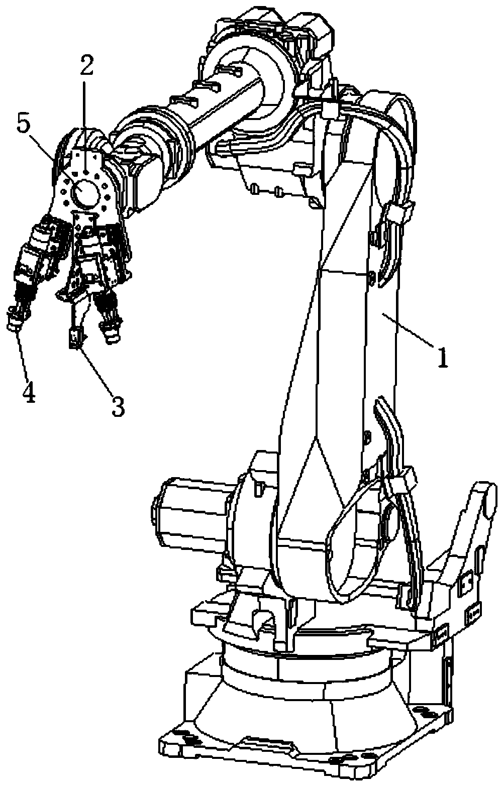
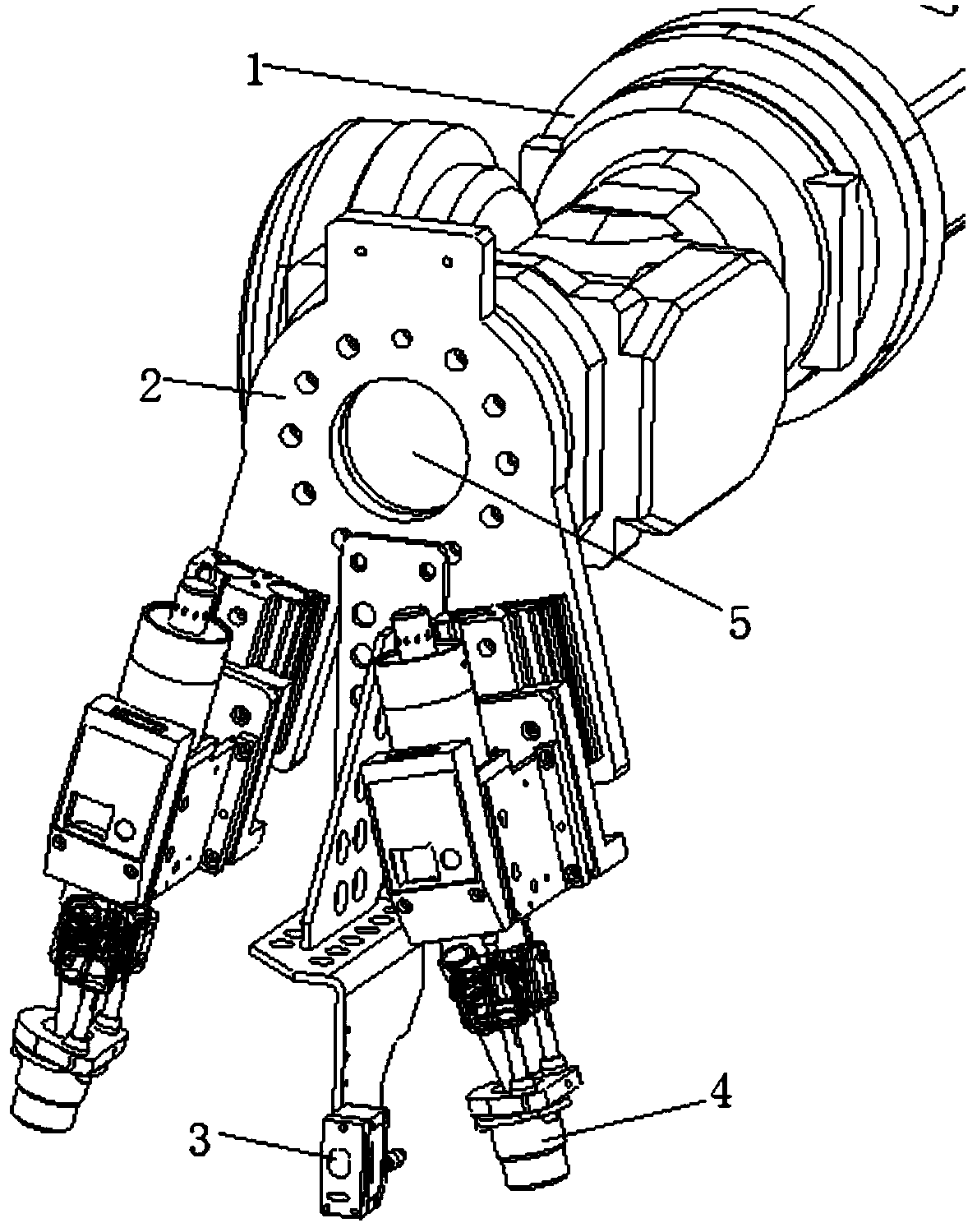
[0023] refer to Figure 1 to Figure 3 , Figure 1 to Figure 3 It is a structural schematic diagram of a specific embodiment of the present invention.

[0024] Such as Figure 1 to Figure 3 As shown, a stud welding laser positioning system includes a multi-axis robot 1, one end of the multi-axis robot 1 is fixed, and the other end of the multi-axis robot 1 is provided with a mounting base 2. A laser position sensor 3 and a stud welding torch 4 are arranged on the installation base 2 .

[0025] Specifically, the installation base 2 is connected to the multi-axis robot 1 through an end rotating shaft 5 , and the laser position sensor 3 and the stud welding torch 4 are arranged along the radial direction of the end rotating shaft 5 . There are multiple stud welding guns 4 and they are respectively used for welding studs of different specifications. It also includes an assembly line platform 6 in which a welding station 7 is arranged, and the multi-axis robot 1 is arranged on o...


PUM


Abstract

The invention discloses a stud welding laser locating system. The stud welding laser locating system comprises a multi-axis robot. One end of the multi-axis robot is fixedly arranged, a mounting baseis arranged at the other end of the multi-axis robot, and a laser position sensor and stud welding guns are arranged on the mounting base. The mounting base is connected with the multi-axis robot through a terminal rotary shaft, and the laser position sensor and the stud welding guns are arranged in the radial direction of the terminal rotary shaft. The multiple stud welding guns are used for welding studs of different specifications. The invention further discloses a working method of the stud welding laser locating system. According to the stud welding laser locating system and the working method thereof, before the studs are welded, supplied workpieces are subjected to laser locating, and the welding positions of the studs can be corrected according to deviations of inner borders of thesupplied workpieces.

Description

technical field [0001] The invention relates to the technical field of stud automatic welding equipment and technology, in particular to a stud welding laser positioning system and its working method. Background technique [0002] In the metal processing industry, in order to splice workpieces of different shapes into products, a welding process is often required. Welding is to connect two or more materials of the same or different materials into one through the bonding and diffusion between atoms or molecules. processing technology. In general, the parts that need to be welded are fused by heating. Due to the heating, the temperature field of the heated part is inconsistent with other unheated parts, which easily leads to deformation of shape and size; in addition, due to the installation accuracy of the workpiece and the size of the workpiece The influence of tolerances will cause tolerances in the processed workpieces, and the tolerances of each workpiece are inconsisten...

Claims


Application Information

Patent Timeline
Patent Type & Authority Applications(China)
IPC IPC(8): B23K9/20B23K9/12B23K9/32
Inventor 余德先
Owner 珠海市福尼斯焊接技术有限公司
Learn More