Piezoelectric-driven passive pliant microclamp

A piezoelectric drive, micro-clamp technology, applied in the field of micro-clamp, can solve the problems of low positioning accuracy of the clamped object, small stroke range of the micro-clamp, uneven force state, etc., to achieve uniform force state and increase the stroke range. , the effect of reducing the size of the structure

Active Publication Date: 2019-05-10
HARBIN INST OF TECH
View PDF7 Cites 4 Cited by
  • Summary
  • Abstract
  • Description
  • Claims
  • Application Information

AI Technical Summary

Problems solved by technology

[0004] The present invention solves the problems that the existing piezoelectric-driven micro-clamps have a small stroke range, low positioning accuracy, and uneven stress state of the clamped object, which causes damage to tiny parts, and further provides a piezoelectric-driven passive and compliant micro-clamp

Method used


Image

  • Piezoelectric-driven passive pliant microclamp
  • Piezoelectric-driven passive pliant microclamp
  • Piezoelectric-driven passive pliant microclamp

Examples


specific Embodiment approach 1

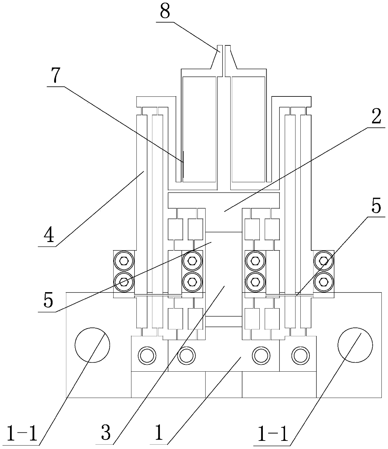
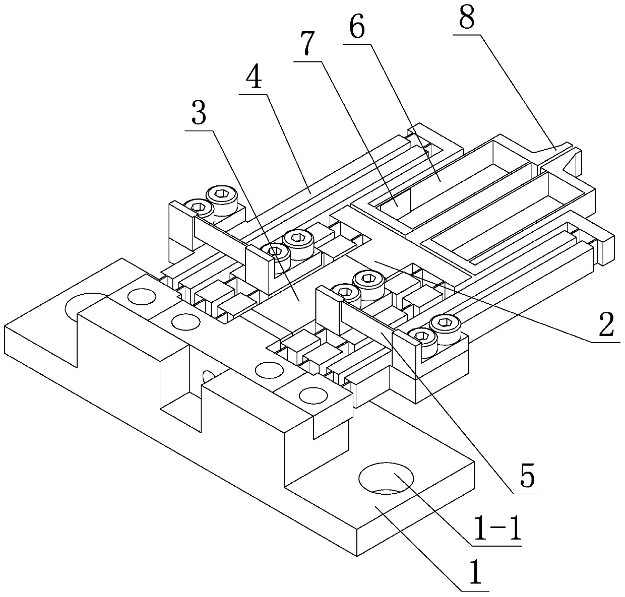
[0018] Specific implementation mode one: as figure 1 and figure 2 As shown, the piezoelectric driven passive compliant micro gripper of this embodiment includes a base 1, a bridge-type amplifying mechanism 2, a piezoelectric ceramic 3, two lever arms 4, two connecting hinges 5, and two clamping arms 6. Two force-measuring strain gauges 7 and two jaws 8. The bridge-type amplifying mechanism 2 is a four-frame structure. The upper and lower ends of the bridge-type amplifying mechanism 2 are the displacement input ends of the bridge-type amplifying mechanism 2. The bridge-type amplifying mechanism The middle part of both sides of 2 is the displacement output end of the bridge type amplifying mechanism 2, the displacement output part of each side of the bridge type amplifying mechanism 2 is a double-layer structure, the piezoelectric ceramic 3 is vertically arranged inside the bridge type amplifying mechanism 2 and the piezoelectric ceramic The two ends of 3 are in contact with t...

specific Embodiment approach 2

[0019] Specific implementation mode two: as figure 1 and figure 2 As shown, the clamping arm 6 in this embodiment has a parallelogram structure, and a load-measuring strain gauge 7 is provided on the inner wall of the parallelogram structure of each clamping arm 6 . In such a design, the piezoelectric-driven passively compliant micro-clamp of the present invention introduces the design concept of passive compliant, and designs the stiffness of the parallelogram clamping arm, so that the position control of the micro-clamp system does not need to rely on the position sensor, and only needs to be opened. Ring control is sufficient, thereby simplifying the system structure. Other components and connections are the same as those in the first embodiment.

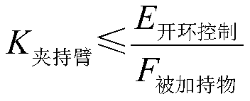
[0020] Clamping arm 6 stiffness design principles:

[0021] The stiffness of the clamping arm 6 is less than or equal to the ratio of the maximum error of the open-loop position control to the maximum bearing force of the obj...

specific Embodiment approach 3

[0025] Specific implementation mode three: as figure 1 and figure 2 As shown, the connection hinge 5 in this embodiment is a sheet-shaped connection hinge. With such a design, the lever arm 4 can be enlarged twice through the leaf hinge 5 to achieve a magnification of 50 times, ensuring the stability of the magnification of the lever arm 4 . Other compositions and connections are the same as those in Embodiment 1 or 2.


PUM


Abstract

The invention discloses a piezoelectric-driven passive pliant microclamp, relates to a microclamp, and solves the problems of narrow travel range and low positioning precision in a traditional piezoelectric-driven microclamp and damage of fine parts caused by nonuniform stress state of clamped matters. A bridge amplifying mechanism is of a four-frame structure; piezoelectric ceramic is verticallyarranged in the bridge amplifying mechanism, and two ends of the piezoelectric ceramic are contacted with the upper and lower ends of the bridge amplifying mechanism; two lever support arms are vertically arranged on two sides of a displacement output end of the bridge amplifying mechanism; the displacement output end of the bridge amplifying mechanism is connected with the lower parts of the level support arms on the same sides through connecting hinges; two clamping arms are arranged side by side, and are positioned right above the bridge amplifying mechanism; the upper part of each lever support arm is connected with one adjacent clamping arm; a clamp port is formed in the upper end of each clamping arm; two clamp ports are oppositely arranged; and measuring force strain pieces are arranged on the two clamping arms. The piezoelectric-driven passive pliant microclamp is used for an execution mechanism of a micro assembly system.

Description

technical field [0001] The invention relates to a micro-clamp, in particular to a passive and flexible micro-clamp driven by piezoelectricity. Background technique [0002] As the executive mechanism of micro-manipulation and micro-assembly systems, micro-clamps are the basic tools for communicating the macro-world and the micro-world, and are widely used in biomedicine, MEMS assembly, aerospace and other fields. In the field of micro-assembly, it is often necessary to use micro-grippers to operate micron-scale tiny parts, so micro-grippers should have large travel and high resolution and keep small structural dimensions. In addition, in order to avoid damage to tiny parts and perform high Accurate assembly requires that the jaws of the microgripper always maintain a parallel relationship during movement; at the same time, online monitoring of the clamping force and position of the jaws is required, and feedback control is performed. [0003] To sum up, the existing piezoel...

Claims


Application Information

Patent Timeline
Patent Type & Authority Applications(China)
IPC IPC(8): B25J7/00
Inventor 董为陈方鑫杜志江
Owner HARBIN INST OF TECH
Why Eureka
Try Eureka