A hot runner nozzle structure for three-layer material injection molding

A technology of three-layer materials and hot runners, applied in the field of auxiliary structures, to achieve the effects of shortening the process flow, streamlining and saving, saving equipment debugging and material turnover time

Active Publication Date: 2020-10-30
HANGZHOU WAHAHA PRECISION MACHINERY
View PDF1 Cites 1 Cited by
  • Summary
  • Abstract
  • Description
  • Claims
  • Application Information

AI Technical Summary

Problems solved by technology

However, this utility model is essentially to save equipment and space and improve production efficiency by adding more injection molding cavities in a set of molds, not to solve the technical problem of multi-layer material overmolding

Method used


Image

  • A hot runner nozzle structure for three-layer material injection molding
  • A hot runner nozzle structure for three-layer material injection molding
  • A hot runner nozzle structure for three-layer material injection molding

Examples


Embodiment 1

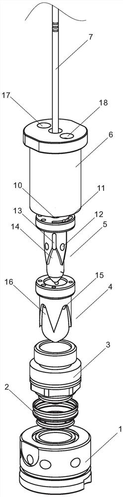
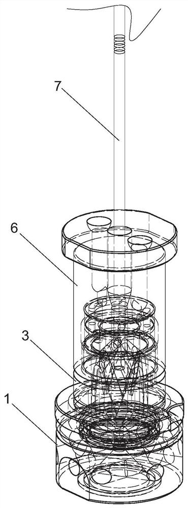
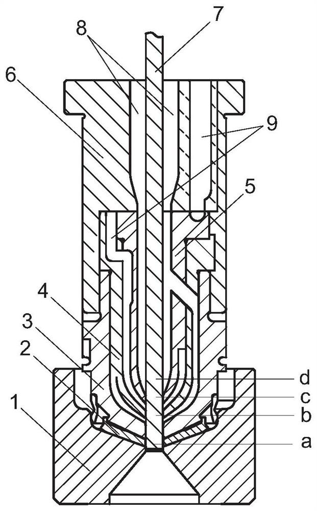
[0026] Such as Figure 1 to Figure 4 As shown, a hot runner nozzle structure of three-layer material injection molding, including cold mold 1, nozzle 3, outer nozzle 4, inner nozzle 5, nozzle seat 6 and valve needle 7, nozzle 3, outer nozzle 4 , the inner nozzle 5 and the nozzle seat 6 are all hollow structures with a central opening at the bottom, the nozzle seat 6, the outer nozzle 4 and the inner nozzle 5 are coaxially nested and matched from the outside to the inside in turn, and the three are provided with a peripheral In the positioning structure, the outer nozzle 4 is coaxially nested and matched with the nozzle 3 at the same time, the nozzle 3 is fixedly connected to the open end of the bottom of the nozzle seat 6, the bottom of the nozzle 3 is embedded in the cavity of the cold mold 1, and the valve needle 7 Along the axis of nozzle 3, outer nozzle 4, inner nozzle 5, and nozzle seat 6, it can slide through the nozzle 3, outer nozzle 4, inner nozzle 5, nozzle seat 6, a...

Embodiment 2

[0029] The present invention is used for bottle caps of glass cans, the base material A is food-grade PP, and the interlayer material B is EVOH. All the other are with embodiment 1.

[0030] When working, after the inner layer of the bottle cap is formed, the valve needle 7 moves directly from the position b above the center opening of the bottom of the nozzle to the position d above the center opening of the bottom of the inner nozzle, and then the bottle cap interlayer and outer layer are formed by controlling the injection pressure.

Embodiment 3

[0032] Interlayer material B is color masterbatch. All the other are with embodiment 1. After the final blow molding of the obtained preform, it has both hygienic safety and high light-shielding performance.


PUM


Abstract

The invention discloses a three-layer material injection molding hot runner injection nozzle structure. The three-layer material injection molding hot runner injection nozzle structure comprises a cold mold, an injection nozzle, an outer injection nozzle, an inner injection nozzle, an injection nozzle base and a valve needle; the injection nozzle, the outer injection nozzle, the inner injection nozzle and the injection nozzle base are each of a hollow structure, and the bottom centers of the injection nozzle, the outer injection nozzle, the inner injection nozzle and the injection nozzle baseare open; the injection nozzle base, the outer injection nozzle and the inner injection nozzle are sequentially and coaxially matched in an embedded and sleeved mode from outside to inside, and a circumferential positioning structure is arranged among the injection nozzle base, the outer injection nozzle and the inner injection nozzle; the outer injection nozzle is also coaxially matched with theinjection nozzle in an embedded and sleeved mode; the injection nozzle is fixedly connected with the bottom opening end of the injection nozzle base; the bottom of the injection nozzle is embedded into a cavity of the cold mold; the valve needle penetrates through the injection nozzle, the outer injection nozzle, the inner injection nozzle and the injection nozzle base along the axis in a slidingmode; the top end of the valve needle is connected with a valve needle drive device; the injection nozzle base and the inner injection nozzle are provided with matrix material runners and interlayer material runners; an interlayer material runner is arranged inside the outer injection nozzle; a matrix material runner is arranged inside the outer injection nozzle; and outlets of the matrix materialrunners are located in the bottom centers of the injection nozzle and the inner injection nozzle. The three-layer material injection molding hot runner injection nozzle structure can shorten the process procedure and greatly improve the production efficiency.

Description

technical field [0001] The invention relates to an accessory structure of injection molding equipment, more specifically, it relates to a hot runner nozzle structure for three-layer material injection molding. Background technique [0002] The packaging materials used for bottled beverages usually include plastic, metal and glass. Among them, plastic bottles are usually produced and processed by injection molding into preforms first, and then blow molding. Since the plastic is thinned during the blow molding process, after filling the beverage, The polymer gap of the plastic allows the gas molecules in some aerated beverages to pass through. After a period of time, a large amount of gas in the beverage will escape out of the bottle, which will greatly affect the taste of the beverage, anti-deterioration, and health care functions. In addition, some added ingredients in some beverages will change their properties after being exposed to too much light. In view of the above si...

Claims


Application Information

Patent Timeline
Patent Type & Authority Patents(China)
IPC IPC(8): B29C45/27B29C45/16
Inventor 梁文杰印雄飞郭太松余细兵
Owner HANGZHOU WAHAHA PRECISION MACHINERY
Why Eureka
Try Eureka