Connecting structure of salt inlet pipe and molten salt storage tank for molten salt storage tank

A technology for connecting structures and storage tanks, applied in the direction of pipes/pipe joints/pipe fittings, pipes, pipe supports, etc., which can solve the problem of different thermal expansion of storage tanks into salt pipes, increase the risk of damage to the connection, and reduce the use of storage tanks. life and other issues, to protect the tank, reduce the risk of damage and instability, and increase flexibility

Active Publication Date: 2019-05-10
ZHEJIANG SUPCON SOLAR TECHNOLOGY CO LTD
View PDF9 Cites 2 Cited by
  • Summary
  • Abstract
  • Description
  • Claims
  • Application Information

AI Technical Summary

Problems solved by technology

[0004] The purpose of the present invention is to provide a connection structure between the salt inlet pipe and the molten salt storage tank for the molten salt storage tank, so as to solve the problem in the prior art that the temperature of the molten salt pipeline and the temperature of the storage tank are not synchronized. The thermal expansion is different from the thermal expansion of the salt inlet pipe, and the stress of the connection between the salt inlet pipe and the storage tank increases. This alternating stress change will reduce the service life of the storage tank and increase the risk of damage to the connection and other technical problems

Method used


Image

  • Connecting structure of salt inlet pipe and molten salt storage tank for molten salt storage tank
  • Connecting structure of salt inlet pipe and molten salt storage tank for molten salt storage tank
  • Connecting structure of salt inlet pipe and molten salt storage tank for molten salt storage tank

Examples


Embodiment Construction

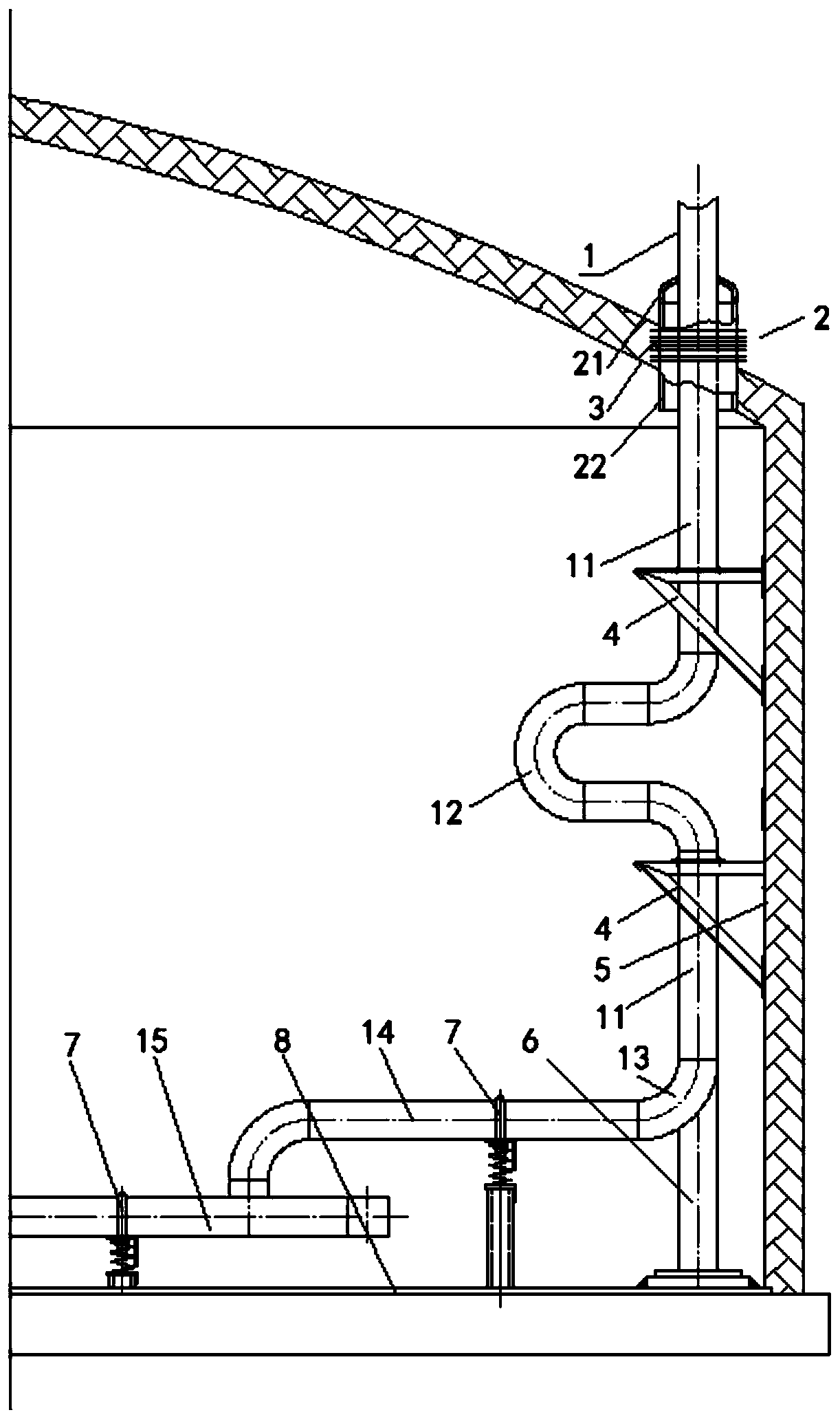
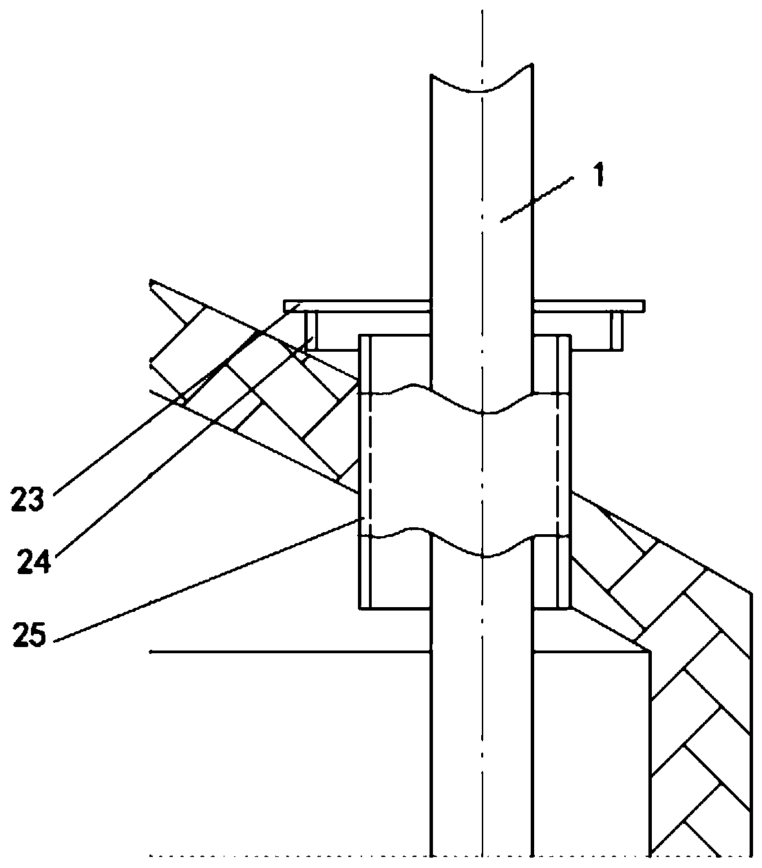
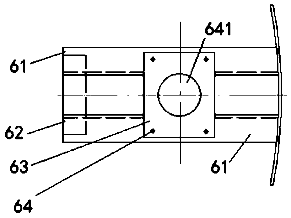
[0044] The following will combine Figure 1 to Figure 7 The connection structure of a salt inlet pipe for a molten salt storage tank and a molten salt storage tank provided by the present invention is described in detail. This embodiment is implemented on the premise of the technical solution of the present invention, and a detailed implementation is given. mode and specific operation process, but the protection scope of the present invention is not limited to the following embodiments, and those skilled in the art can modify and refine it within the scope of not changing the spirit and content of the present invention.

[0045] Please refer to figure 1 , a connection structure for the salt inlet pipe of the molten salt storage tank and the molten salt storage tank, the salt inlet pipe 1 extends from the tank top 3 of the storage tank, and at the top of the storage tank, the The salt inlet pipe 1 is connected with the tank top 3 of the storage tank through the expansion conne...


PUM


Abstract

The invention relates to a connecting structure for a salt inlet pipe and a molten salt storage tank of the molten salt storage tank. The salt inlet pipe extends into the tank top of the storage tank,at the top of the storage tank, and the salt inlet pipe is connected with the tank top of the storage tank through an expansion connection structure; in the middle of the storage tank, a vertical pipe section of the salt inlet pipe is connected with the inner wall of the storage tank through a salt inlet pipe support, the vertical pipe section can freely move in the radial direction of the storage tank during salt feeding of the salt inlet pipe; at the bottom of the storage tank, a horizontal pipe section of the salt inlet pipe is elastically connected with a bottom plate of the storage tankthrough an elastic support, one end of the elastic support is arranged on the bottom plate of the storage tank, the other end of the elastic support is used for supporting the horizontal pipe section,the salt inlet pipe is used for feeding salt, the horizontal pipe section can freely move in the vertical direction, the problems that in the prior art, due to the fact that the temperature of the molten salt pipeline is not synchronous with the temperature change of the storage tank, the thermal expansion amount of the storage tank and the thermal expansion amount of the salt inlet pipe are different, the service life of the storage tank is reduced, the damage risk of the connection part is increased and the like are solved.

Description

technical field [0001] The invention relates to the field of solar thermal power generation, in particular to a connection structure of a salt inlet pipe for a molten salt storage tank and a molten salt storage tank. Background technique [0002] Solar thermal power generation technology uses solar energy to generate electricity, which is an important direction for large-scale utilization of solar energy. Its most competitive advantage is that it is easy to combine with heat storage systems. influences. Molten salt has the characteristics of high operating temperature, wide temperature range, good flow characteristics, and large heat capacity. It can be used for large-scale heat storage in solar thermal power plants and is currently the most widely used solar heat storage medium. [0003] In the heat storage system of the solar thermal power station, the molten salt storage tank is one of the key equipments. Due to the instability of solar radiation, the temperature of the...

Claims


Application Information

Patent Timeline
IPC IPC(8): B65D88/54F16L5/00F16L3/205F16L3/08
Inventor 金建祥徐能唐亚平周慧唐娟余志勇毕文剑童郭凯
Owner ZHEJIANG SUPCON SOLAR TECHNOLOGY CO LTD
Why Eureka
Try Eureka