Marine frequency converter hoisting tool

A hoisting tool and frequency converter technology, which is applied to hoisting devices, portable hoisting devices, etc., can solve the problems of inconvenient use of hoisting tools, and achieve the effects of protecting cargo safety, improving stability and occupying a small area.

Active Publication Date: 2019-05-10
POLAR RES INST OF CHINA
View PDF8 Cites 1 Cited by
  • Summary
  • Abstract
  • Description
  • Claims
  • Application Information

AI Technical Summary

Problems solved by technology

[0007] The purpose of the present invention is to provide a marine inverter hoisting tool, through the anti-shake setting, the inverter is stabilized during the hoisting process, and the hoisting process is simplified at the same time, the invention solves the technical problem of inconvenient use of the existing marine hoisting tools

Method used


Image

  • Marine frequency converter hoisting tool
  • Marine frequency converter hoisting tool
  • Marine frequency converter hoisting tool

Examples


Embodiment 1

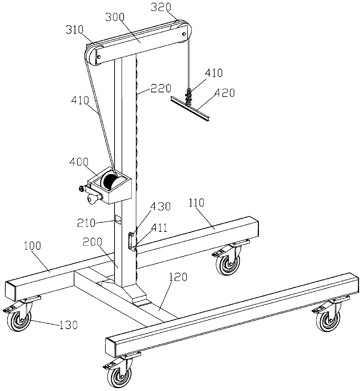
[0051] Such as Figure 1-8 As shown, the present invention provides a marine frequency converter hoisting tool. The base 100 is an H-shaped structure, including support beams 110 and middle beams 120 on both sides. The bottom of the base 100 is provided with moving wheels 130. Heavy-duty casters with brakes with a force of 300 kg, two directional and two swivel, allow the lifting tool to move freely or turn, and remain stable when stationary.

[0052] The load-bearing bracket 200 is longitudinally fixed on the base 100, specifically installed on the middle beam 120 of the H-shaped structure of the base 100, and the middle beam 120 is close to the tail of the H-shaped structure to balance the hoisting tool during the hoisting process. center of gravity.

[0053] A top beam 300 is horizontally arranged on the top of the load-bearing bracket 200, and the length direction of the top beam 300 is consistent with the length direction of the base 100. end.

[0054] The driving mech...

Embodiment 2

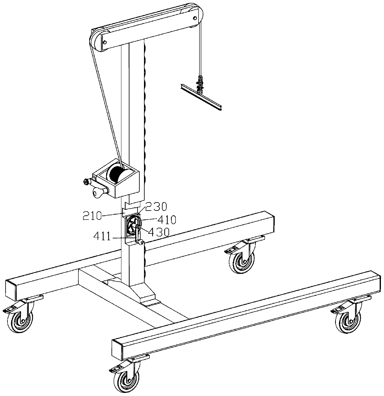
[0082] Such as Figure 9-11 As shown, on the basis of the first embodiment, the lifting function of the lifting tool itself is added.

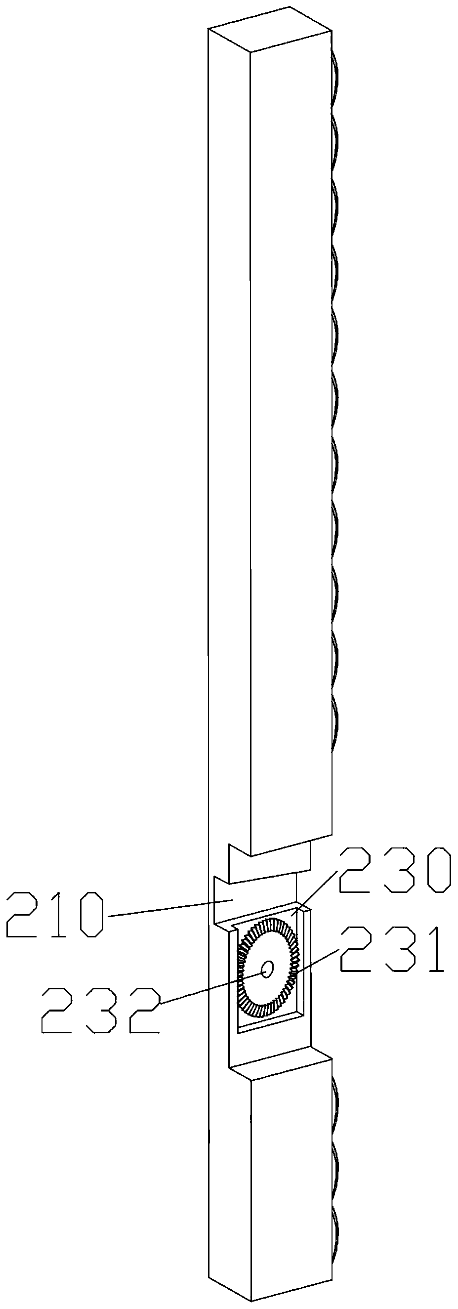
[0083] Under the premise of ensuring that the load-bearing bracket 200 has sufficient bearing capacity, the load-bearing bracket 200 at the upper end of the through hole 210 is a hollow structure, similar to a tubular structure, by analyzing the axial and radial force distribution of the square tube, etc., The material, performance and size of the materials used are all calculated to ensure sufficient bearing capacity without being too bulky and unbalanced, so that the hoisted heavy modules can move freely and safely in the small cabin.

[0084] A screw 610 is longitudinally arranged in the cavity of the load-bearing bracket 200, and the bottom of the screw 610 is rotatably mounted on the bottom of the cavity of the load-bearing bracket 200 through the second bearing 630, and a slider 620 is installed on the screw 610, thereby forming a The s...


PUM


Abstract

The invention discloses a marine frequency converter hoisting tool. The marine frequency converter hoisting tool comprises main components including a base, a bearing support, a driving mechanism, movable wheels and the like. The movable wheels are arranged at the bottom of the base. The bearing support is longitudinally fixed to the base, and a pulley block is mounted at the top of the bearing support. The driving mechanism is mounted on the bearing support, and the leading-out end of the driving mechanism is connected with a frequency converter to be hoisted downwards through the pulley block. A through hole is formed in the bearing support in a penetrating manner, and the direction of the through hole is consistent with the line connecting direction of the pulley block. A cavity is formed in the bearing support at the bottom of the through hole, and a rotary disc mechanism is longitudinally mounted in the cavity. A limiting beam is movably and telescopically arranged in the throughhole, and the upper end of the rotary disc mechanism protrudes into the through hole and is in linkage with the limiting beam. The front end of the limiting beam abuts against the frequency converter.The marine frequency converter hoisting tool solves the technical problem a proper hoisting tool is in lack when a large frequency converter of an existing ship is repaired is solved.

Description

technical field [0001] The invention relates to the technical field of marine tools, in particular to a marine frequency converter hoisting tool. Background technique [0002] In recent years, with the rapid development of power electronic devices, frequency conversion technology, and direct torque control systems, more and more ships use pod-type electric propulsion systems. The core component of this system is the frequency converter. Due to the harsh environment on board, the frequency converter will be affected by temperature, humidity, vibration, dust and corrosive gas during use, resulting in changes in the performance of the frequency converter. Therefore, it is necessary to regularly maintain and maintain the frequency converter in order to reduce the frequency converter failure rate, reduce maintenance costs and prolong the service life. [0003] The main propulsion power of the electric propulsion ship participated by the applicant comes from two sets of azimuth t...

Claims


Application Information

Patent Timeline
Patent Type & Authority Applications(China)
IPC IPC(8): B66D3/06B66D3/10
Inventor 黄嵘刘志兵孙凤鸣祖成弟李文明郭青云魏海峰张懿李垣江
Owner POLAR RES INST OF CHINA
Why Eureka
Try Eureka